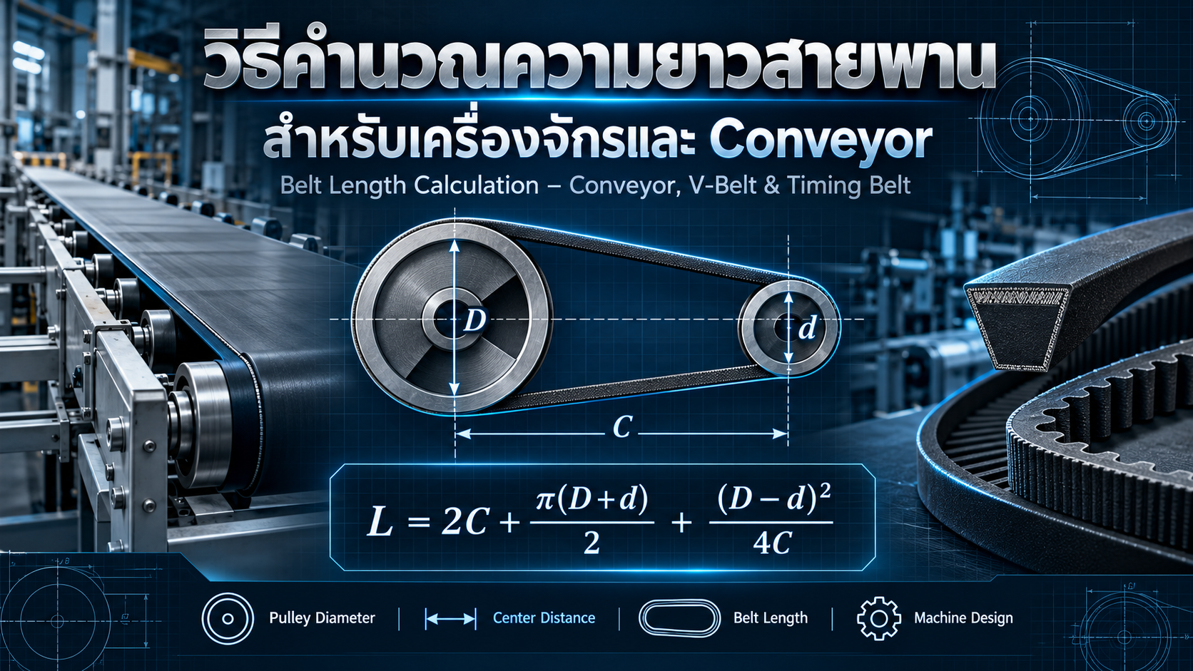
How to Calculate Belt Length for Conveyors, V-Belts and Timing Belts
A Practical Guide to Belt Length Formulas, Pulley Diameters, Center Distance and Industrial Machinery Design
Belt systems are widely used in industrial machinery, material handling equipment and automated production lines.
Common applications include conveyor systems, motor-driven machinery, timing belt mechanisms and industrial power transmission systems.
One of the essential steps in designing these systems is determining the correct belt length.
An incorrectly selected belt may cause installation problems, excessive tension, belt slipping, premature wear or difficulty maintaining proper operating conditions.
Accurate belt length calculations help engineers select suitable standard belts, determine pulley center distances and design effective belt tensioning arrangements.
This article explains the formulas and practical considerations for calculating belt length in conveyor systems, V-belt drives and timing belt mechanisms.
1. What Is Belt Length?
Belt Length is the total length of a belt measured along a defined reference line around its pulley system.
For an endless belt, this represents the closed-loop length following the designed belt path.
However, different belt types use different reference length definitions.
Common examples include:
Pitch Length
Datum Length
Outside Length
Inside Length
These measurements are not necessarily interchangeable.
The correct length definition must be selected according to the belt manufacturer's specifications.
Why Is Belt Length Calculation Important?
Accurate calculation supports:
Correct belt selection
Appropriate pulley spacing
Proper installation
Suitable tension adjustment
Improved maintenance planning
Reduced replacement errors
Consistent mechanical system design
2. Common Industrial Belt Types
V-Belt
V-belts transfer mechanical power between grooved pulleys using friction.
They are commonly found in motors, pumps, fans and industrial power transmission equipment.
Timing Belt
Timing belts use teeth that engage with matching pulley teeth.
They are commonly used in automation mechanisms, servo-driven systems, positioning equipment and synchronized drives.
Flat Belt
Flat belts may be used for power transmission or material handling applications, depending on their construction.
Conveyor Belt
Conveyor belts transport materials and products through industrial processing systems.
Common applications include assembly lines, packaging equipment, inspection conveyors and material handling systems.
3. Basic Belt Length Calculation Parameters
For a conventional two-pulley open belt drive, the main parameters are:
D: Effective diameter of the larger pulley (mm)
d: Effective diameter of the smaller pulley (mm)
C: Center distance between the two pulley axes (mm)
L: Calculated belt length (mm)
All dimensions must use consistent units.
For synchronous belts, pulley pitch diameters must be used.
For V-belts, the appropriate reference diameter depends on the belt profile and manufacturer's length designation system.
4. Open Belt Length Calculation Formula
A commonly used approximate formula for an open belt drive with two pulleys is:
L ≈ 2C + π(D + d)/2 + (D − d)²/(4C)
Where:
L = Belt length
C = Pulley center distance
D = Larger pulley reference diameter
d = Smaller pulley reference diameter
The formula consists of three terms.
2C: Represents the approximate total length of the two straight belt sections.
π(D + d)/2: Represents the approximate combined pulley wrap length.
(D − d)²/(4C): Corrects for the difference between the pulley diameters.
This formula is widely used for preliminary belt drive design.
It becomes less accurate when the pulley diameter difference is large relative to the center distance.
More exact tangent geometry may be used where necessary.
5. Example: V-Belt Length Calculation
Consider an industrial belt drive with the following dimensions:
Large Pulley Diameter = 200 mm
Small Pulley Diameter = 100 mm
Center Distance = 500 mm
Using:
L ≈ 2C + π(D + d)/2 + (D − d)²/(4C)
Step 1: Straight Belt Sections
2C = 2 × 500
2C = 1,000 mm
Step 2: Pulley Wrap Term
π(D + d)/2
= π(200 + 100)/2
≈ 471.24 mm
Step 3: Diameter Correction
(D − d)²/(4C)
= (200 − 100)²/(4 × 500)
= 5 mm
Step 4: Total Calculated Length
L ≈ 1,000 + 471.24 + 5
L ≈ 1,476.24 mm
The estimated belt length is approximately 1,476 mm.
This value should be compared with available standard belt lengths from the selected manufacturer.
The required pulley center distance and tensioning arrangement must then be verified.
6. Calculating Center Distance from a Standard Belt Length
In some machine designs, a standard belt length is selected before the final pulley spacing is established.
The open-belt approximation can be rearranged to estimate the required center distance.
Define:
B = L − π(D + d)/2
Then:
C ≈ [B + √(B² − 2(D − d)²)] / 4
This expression gives the usual longer-center-distance solution of the approximate relationship, provided the geometry is valid.
Example
Assume:
Standard reference belt length = 1,500 mm
Larger pulley diameter = 200 mm
Smaller pulley diameter = 100 mm
First calculate:
B ≈ 1,028.76 mm
Then:
C ≈ 511.94 mm
The estimated center distance is approximately 511.94 mm.
Compared with the original 500 mm center distance, selecting the 1,500 mm reference length requires an adjustment of approximately 11.94 mm.
Actual installation must also provide sufficient travel for belt fitting and correct tensioning.
7. Belt Length for Equal-Diameter Pulleys
When both pulleys have the same reference diameter:
D = d
The general formula simplifies to:
L = 2C + πD
This is an exact geometrical relationship for a simple open belt path around two equal circular pulleys, measured using a consistent effective running diameter.
Example
Assume:
Pulley Diameter = 150 mm
Center Distance = 600 mm
L = 2(600) + π(150)
L ≈ 1,671.24 mm
This relationship is particularly useful for simple two-pulley conveyor layouts.
8. Conveyor Belt Length Calculation
A basic belt conveyor consists of a drive pulley, tail pulley, supporting structure and an endless conveyor belt.
For a simple two-pulley conveyor with equal pulley diameters:
L = 2C + πD
Example: Industrial Belt Conveyor
Assume:
Conveyor Center Distance = 4,000 mm
Drive Pulley Diameter = 200 mm
Tail Pulley Diameter = 200 mm
Then:
L = 2(4,000) + π(200)
L ≈ 8,628.32 mm
Or:
L ≈ 8.628 m
This is the geometrical belt path length for the assumed simple arrangement.
If the conveyor uses different pulley diameters, the unequal-pulley formula should be used.
If the system includes additional snub pulleys, bend pulleys or a take-up arrangement that changes the belt path, a complete geometric calculation is necessary.
The length of an unjoined belt required for installation may also differ from the final endless-loop length because of the manufacturer's splicing method and installation procedure.
9. Timing Belt Length Calculation
Timing belts require additional consideration because belt teeth must engage correctly with pulley teeth.
Important parameters include:
Belt Pitch
Pulley Tooth Count
Pulley Pitch Diameter
Center Distance
Belt Tooth Count
Pulley Pitch Diameter
The pitch diameter of a timing pulley can be calculated using:
Dp = Z × p / π
Where:
Dp = Pitch Diameter
Z = Number of Pulley Teeth
p = Belt Pitch
Timing Belt Pitch Length
For a two-pulley open drive:
Lp ≈ 2C + π(Dp1 + Dp2)/2 + (Dp1 − Dp2)²/(4C)
The belt tooth count is:
Zbelt = Lp / p
The final belt tooth count must be an integer and correspond to an available manufacturer product.
Timing Belt Example
Assume:
Belt Pitch = 5 mm
First Pulley = 24 Teeth
Second Pulley = 24 Teeth
Center Distance = 400 mm
Pitch Diameter:
Dp = (24 × 5)/π
Dp ≈ 38.20 mm
Since both pulleys have the same pitch diameter:
Lp = 2C + πDp
= 2(400) + 120
Lp = 920 mm
Belt Tooth Count:
Zbelt = 920/5
Zbelt = 184 Teeth
The theoretical requirement is a 920 mm pitch-length timing belt with 184 teeth.
The actual belt must be selected from the manufacturer's available profiles and lengths, and the installation geometry must be verified.
10. Crossed Belt Drive Calculation
For suitable crossed-belt arrangements, an approximate belt length formula is:
L ≈ 2C + π(D + d)/2 + (D + d)²/(4C)
Unlike the standard open-belt relationship, the correction term uses the sum of the pulley diameters.
Crossed-belt drives require additional considerations, including belt twisting, clearance, pulley geometry and compatibility.
This arrangement is not suitable for every belt type.
11. Calculating Belt Length for Multiple Pulleys
Industrial conveyors and automated machines may contain several pulleys.
Examples include:
Drive Pulley
Tail Pulley
Snub Pulley
Bend Pulley
Take-Up Pulley
For these systems, total belt length must be calculated using the actual belt path.
The general principle is:
Total Belt Length = Total Straight Sections + Total Pulley Contact Arcs
For an individual pulley:
Arc Length = r × θ
Where:
r = Pulley reference radius
θ = Belt wrap angle in radians
The calculation procedure is:
Determine all pulley center coordinates.
Identify pulley reference diameters.
Define the actual belt routing.
Calculate tangent points between pulleys.
Determine straight belt segment lengths.
Calculate each pulley contact arc.
Sum all segment lengths.
Verify the take-up position and installation requirements.
CAD software can be used to model complex pulley arrangements and verify the total belt path.
12. Understanding Belt Length Definitions
Pitch Length
The belt length measured along its pitch line.
This is especially important for timing belts because it directly relates to belt pitch and tooth count.
Datum Length
A reference length defined by the applicable belt standard and manufacturer.
Commonly used for certain V-belt profiles.
Outside Length
A length measurement based on the outer belt surface according to the manufacturer's measurement system.
Inside Length
A length measurement based on the inner belt surface.
These length definitions must not be substituted for one another without using the appropriate manufacturer's conversion information.
13. Belt Tension and Take-Up Considerations
Correct belt length selection must be coordinated with the tensioning system.
Typical arrangements include:
Adjustable Motor Slide Base
Screw Take-Up
Spring Take-Up
Gravity Take-Up
The required take-up travel depends on the belt construction, operating loads, machine geometry and installation requirements.
For V-belts and timing belts, the selected standard length should be coordinated with an adjustable center distance where required.
For conveyor belts, installation procedures may require additional considerations related to belt elongation, splice preparation, take-up positioning and final tension.
A fixed percentage should not automatically be added to every calculated belt length.
The final belt order length must follow the selected belt manufacturer's and installer's requirements.
14. Common Belt Length Calculation Mistakes
Using the Wrong Pulley Diameter
Pitch diameter, datum diameter and outside diameter are not always interchangeable.
Measuring the Wrong Center Distance
Center distance is measured between pulley axes, not between the nearest pulley surfaces.
Ignoring Belt Type
V-belts, timing belts and conveyor belts have different design and length specifications.
Ignoring Standard Belt Lengths
Calculated lengths may not correspond to available commercial products.
Insufficient Tensioning Adjustment
A belt may have the correct nominal length but still be difficult to install or tension.
Ignoring Additional Pulleys
A two-pulley formula cannot describe a belt path modified by multiple bend or snub pulleys.
Applying Arbitrary Length Allowances
Adding a percentage without considering the take-up system can result in excessive or insufficient belt length.
Ignoring Power Transmission Capacity
Correct belt length does not guarantee adequate torque or power transmission capability.
Incorrect Pulley Alignment
Misaligned pulleys may produce belt tracking problems and premature wear.
15. Belt Length Formula Summary
| Application | Formula |
|---|---|
| Open Belt, Unequal Pulleys | L ≈ 2C + π(D+d)/2 + (D−d)²/(4C) |
| Open Belt, Equal Pulleys | L = 2C + πD |
| Crossed Belt | L ≈ 2C + π(D+d)/2 + (D+d)²/(4C) |
| Timing Pulley Diameter | Dp = Zp/π |
| Timing Belt Tooth Count | Zbelt = Lp/p |
| Pulley Contact Arc | Larc = rθ |
| Multiple Pulley Arrangement | Sum of straight segments and pulley contact arcs |
These formulas support geometric belt length calculations.
Final equipment selection also requires consideration of operating speed, belt tension, transmitted load, pulley alignment and relevant manufacturer specifications.
16. Frequently Asked Questions
What Is the Formula for Belt Length?
For a typical two-pulley open belt drive:
L ≈ 2C + π(D+d)/2 + (D−d)²/(4C)
How Do You Calculate Belt Length for Equal Pulleys?
Use:
L = 2C + πD
Can the Same Formula Be Used for Conveyor Belts?
Yes, for simple two-pulley geometry using appropriate effective diameters. More complex conveyors require full belt-path calculations.
How Is Timing Belt Length Determined?
Timing belt length is calculated along the pitch line and must correspond to an integer number of belt teeth.
Why Is the Calculated Length Different from a Catalogue Size?
Manufacturers supply standard lengths. The machine's center distance or belt selection may need adjustment.
Should Extra Length Be Added for Tensioning?
Not automatically. Take-up requirements and installation allowances must be based on the belt type, actual system design and manufacturer's instructions.
17. Conclusion
Accurate belt length calculation is an important part of industrial machinery and conveyor design.
The essential parameters are pulley reference diameters and the center distance between rotating axes.
For a conventional two-pulley open belt drive, the approximate relationship is:
L ≈ 2C + π(D+d)/2 + (D−d)²/(4C)
For equal-diameter pulleys, it simplifies to:
L = 2C + πD
Timing belt calculations additionally require pitch and tooth-count verification.
However, selecting the correct belt involves more than calculating its geometric length.
Engineers must also evaluate available standard sizes, belt tension, drive power, operating speed, pulley alignment, adjustment travel and maintenance requirements.
A properly designed belt system combines accurate geometry, suitable component selection and correct installation to achieve reliable industrial performance.
AC DESIGN AND DEVELOPMENT – Conveyor & Industrial Automation Solutions
AC DESIGN AND DEVELOPMENT CO., LTD. provides custom industrial engineering and manufacturing solutions.
Our services include:
Conveyor System Design and Manufacturing
Automation Machine Design and Manufacturing
Custom Jig & Fixture
Machine Parts Manufacturing
Industrial Steel Structures
Custom Engineering Solutions
We focus on practical machine design, reliable mechanical systems and manufacturing solutions that support production efficiency.
Engineering and Industrial Machinery Solutions Across Thailand
Website: https://acdesignanddevelopment.com/
Tel: +66 82-210-0792
Technical Disclaimer: This article is intended for engineering education. All belt lengths, pulley dimensions, adjustment allowances and equipment specifications must be verified against the relevant manufacturer documentation before manufacturing or installation.