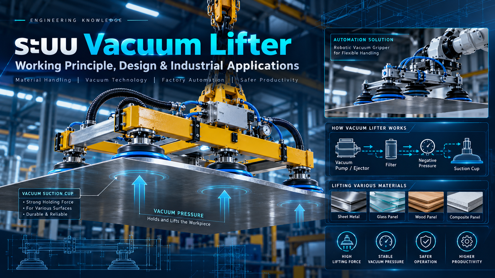
What Is a Vacuum Lifter? Working Principles, Design and Industrial Applications
Understanding Vacuum Suction Cups, Vacuum Pumps, Ejectors, Lifting Force Calculations, Safety Systems and Automation Applications
Vacuum lifting technology plays an important role in modern industrial material handling and automated manufacturing.
Moving large, heavy or delicate workpieces can be challenging when conventional mechanical gripping methods are unsuitable.
Examples include sheet metal, glass panels, aluminum plates, plastic components, packaging materials and products requiring non-invasive handling.
A Vacuum Lifter provides an alternative method by using a pressure difference between atmospheric air and a vacuum gripping surface to generate holding force.
Vacuum lifting systems are widely used with overhead cranes, lifting manipulators, robotic arms, gantry systems and automated production equipment.
However, reliable vacuum lifting requires careful consideration of load capacity, suction area, surface conditions, acceleration, leakage and safety measures.
This article explains the principles, major components, calculations, selection criteria and industrial applications of vacuum lifting systems.
1. What Is a Vacuum Lifter?
A Vacuum Lifter is a device or system that uses pressure below the surrounding atmospheric pressure to grip and lift a workpiece.
The system generally includes a vacuum generator, suction cups, hoses, valves, sensors and a supporting mechanical structure.
When the suction cup contacts a suitable workpiece surface, air is removed from the sealed region.
The resulting pressure difference generates a force that holds the suction cup against the workpiece.
Common Applications
Sheet Metal Lifting
Glass Panel Handling
Aluminum Plate Handling
Robot Pick and Place
CNC Machine Loading
Packaging Automation
Palletizing Systems
Industrial Material Handling
The suitability of vacuum lifting depends on the material, geometry, surface condition, load direction and system design.
2. How Does a Vacuum Lifter Work?
Vacuum lifting is based on the pressure differential between atmospheric pressure and the lower pressure inside a sealed suction cup.
The theoretical holding force is calculated using:
F = ΔP × A
Where:
F = Theoretical holding force (N)
ΔP = Pressure difference (Pa)
A = Effective suction area (m²)
The larger the pressure difference or effective suction area, the greater the theoretical holding force.
Basic Operating Sequence
Position the suction cups against the workpiece.
Activate the vacuum generator.
Remove air from the suction cup cavities.
Monitor the vacuum level.
Verify the required gripping conditions.
Lift and transfer the workpiece.
Place the workpiece on a suitable support.
Release the vacuum under controlled conditions.
Vacuum generation alone does not establish that a workpiece is safe to lift. The control and safety requirements must be verified according to the application.
3. Main Components of a Vacuum Lifter
Vacuum Suction Cup
The suction cup provides the sealing surface between the lifting equipment and the workpiece.
Typical materials include NBR, silicone, polyurethane and other elastomers selected for specific applications.
Vacuum Pump
A vacuum pump removes air from the system and maintains the required vacuum conditions.
Electrically driven pumps are commonly used in centralized vacuum systems and selected lifting applications.
Vacuum Ejector
A vacuum ejector uses compressed air and the Venturi principle to generate suction.
It is commonly used in compact automation systems and robotic end effectors.
Vacuum Filter
Filters protect vacuum equipment from dust, particles and other contaminants.
Vacuum Sensor
Vacuum sensors measure system pressure and provide monitoring signals to the control system.
Vacuum Valve
Valves regulate vacuum generation, isolation and controlled release.
Vacuum Reservoir
A reservoir can form part of a vacuum retention arrangement, subject to appropriate engineering design and verification.
Lifting Frame
The supporting frame transfers mechanical loads between the suction cups and the lifting device.
4. Types of Vacuum Lifting Systems
Crane-Mounted Vacuum Lifter
Designed to lift and transport workpieces using a crane or hoist.
Typical applications include large metal sheets and glass panels.
Such equipment may fall within applicable below-the-hook lifting equipment standards.
Vacuum Tube Lifter
Uses vacuum-assisted handling mechanisms to help operators lift and move suitable loads.
Typical applications include boxes, bags and packaging materials.
Robot Vacuum Gripper
A vacuum end effector mounted on an industrial robot for automated handling.
Applications include pick and place, machine tending and palletizing.
Gantry Vacuum Handling System
Uses a vacuum gripper attached to a Cartesian or gantry motion system.
It is suitable for defined material transfer paths.
Tilting Vacuum Lifter
Designed to rotate or tilt workpieces between orientations.
Additional calculations are required for friction, shear forces, moments and load distribution.
5. Vacuum Lifting Force Calculation
Consider a simplified example.
A vacuum gripping system uses four circular suction cups to lift a 50 kg metal sheet.
Assume:
Workpiece mass = 50 kg
Number of suction cups = 4
Effective suction diameter = 80 mm
Pressure difference = 60 kPa
Smooth, non-porous horizontal workpiece
Full sealing and equal load-sharing assumptions
Step 1: Calculate the Effective Area
For one circular suction cup:
A = πD² / 4
D = 0.08 m
A ≈ 0.005027 m²
Step 2: Calculate the Force per Cup
F = 60,000 × 0.005027
F ≈ 301.6 N
Step 3: Calculate the Total Theoretical Force
F_total = 301.6 × 4
F_total ≈ 1,206.4 N
Step 4: Calculate the Workpiece Weight
W = mg
W = 50 × 9.81
W = 490.5 N
Step 5: Compare the Forces
The theoretical holding-force-to-weight ratio is:
1,206.4 / 490.5 ≈ 2.46
This result represents an idealized static calculation.
It is not a certified lifting capacity or an approved Working Load Limit.
Actual equipment design must account for effective suction areas, imperfect sealing, unequal load distribution, dynamic loads, loss of vacuum and applicable safety criteria.
Effect of Acceleration
If the same workpiece accelerates vertically upward at 2 m/s²:
F_required = m(g + a)
= 50 × (9.81 + 2)
F_required = 590.5 N
If a hypothetical design factor of 2 is applied for this simplified example:
Target Force = 1,181 N
The idealized total suction force of approximately 1,206 N is only slightly above that target.
This illustrates why a simple static force calculation is not sufficient for selecting a lifting system.
The actual acceptance criteria must come from the applicable design requirements and verified equipment performance.
6. Horizontal vs. Vertical Workpiece Handling
The orientation of the workpiece significantly affects the required gripping force.
Horizontal Workpiece
When suction cups grip the upper surface of a horizontal plate and lift vertically, the workpiece weight acts approximately along the suction direction.
Vertical Workpiece
When suction cups grip a vertical surface, the workpiece weight acts primarily along the contact plane.
Friction becomes a major factor in preventing the workpiece from sliding.
A simplified friction relationship is:
F_friction = μN
Where:
μ = Coefficient of friction
N = Normal holding force
Using the previous theoretical force of 1,206 N and an assumed friction coefficient of 0.4:
F_friction ≈ 482 N
This is below the 490.5 N static weight of the 50 kg workpiece, even before considering acceleration and safety factors.
Therefore, a suction arrangement suitable for lifting a horizontal plate may not be suitable for holding the same plate vertically.
Actual friction coefficients and equipment ratings must be verified for the workpiece and suction cup combination.
7. How to Select Vacuum Suction Cups
The correct suction cup depends on the geometry and surface characteristics of the workpiece.
Flat Suction Cups
Suitable for many smooth and relatively rigid surfaces, including metal, glass and plastic.
Bellows Suction Cups
Provide axial flexibility and can accommodate certain height variations.
Oval Suction Cups
Useful for narrow or elongated gripping areas.
Foam Grippers
Can accommodate selected uneven or porous surfaces, depending on the vacuum flow capacity and sealing properties.
Specialized Suction Cups
Designed for applications involving curved surfaces, delicate products or unusual materials.
Selection Factors
Workpiece mass and dimensions
Surface roughness and porosity
Contact area
Temperature
Oil and contamination
Lifting orientation
Acceleration
Center of gravity
Cup material compatibility
Required operating cycle time
8. Vacuum Pump vs. Vacuum Ejector
Vacuum pumps and ejectors generate vacuum using different energy sources.
| Feature | Vacuum Pump | Vacuum Ejector |
|---|---|---|
| Energy Source | Usually electric motor | Compressed air |
| Operating Principle | Mechanical vacuum generation | Venturi effect |
| Installation | Centralized or localized | Compact, often near gripping point |
| Typical Application | Lifting and handling systems | Robotic and pneumatic automation |
| Main Considerations | Vacuum level, flow, maintenance | Air consumption, pressure, flow |
| Load Retention Safety | Requires application-specific design | Requires application-specific design |
A vacuum ejector can be convenient when compressed air is already available.
A vacuum pump may be more appropriate for some systems requiring centralized vacuum generation.
Neither option is inherently safer without the necessary monitoring and protective measures.
9. Vacuum Level and Suction Flow
Vacuum system selection involves two different performance characteristics.
Vacuum Level describes the pressure difference available for creating holding force.
Suction Flow describes the amount of air that the system can remove under specified conditions.
Non-Porous Workpieces
Smooth metal, glass and other well-sealed surfaces may require comparatively low continuous air flow once the required vacuum is established.
Porous Workpieces
Cardboard, foam and other air-permeable materials allow continuous leakage into the gripping system.
These applications may require high suction flow to maintain sufficient vacuum.
A pump with a high maximum vacuum rating may still be unsuitable if its flow capacity cannot compensate for leakage.
10. Vacuum Lifter Safety Systems
A major risk associated with vacuum lifting is loss of holding force while a load is suspended or moving.
Depending on the equipment, the safety system may include:
Vacuum Monitoring
Measure the vacuum level and verify the necessary conditions before lifting.
Low Vacuum Warning
Provide appropriate warning when the measured vacuum drops below the permitted range.
Vacuum Reservoir and Check Valves
Support vacuum retention when designed and validated for the specified failure conditions.
Redundant Vacuum Arrangements
Reduce the impact of selected faults when redundancy is required by the risk assessment and applicable standards.
Mechanical Load Retention
Provide supplementary support or restraint when required for the application.
Controlled Release
Prevent unintended workpiece release by verifying suitable support and operating conditions before activating the release sequence.
Emergency Stop Function
An emergency stop must lead to an appropriately assessed safe condition.
Automatically venting vacuum during an emergency stop may cause a suspended workpiece to fall and must not be assumed safe.
Inspection and Testing
Load capacity, safety functions, warnings, retention performance and the mechanical structure must be verified according to the applicable requirements.
A theoretical holding-force calculation is not a substitute for lifting equipment testing or certification.
11. Important Vacuum Lifting Standards
ASME B30.20 – Below-the-Hook Lifting Devices
Addresses marking, construction, installation, inspection, testing, maintenance and operation of below-the-hook lifting devices within its scope.
ASME BTH-1 – Design of Below-the-Hook Lifting Devices
Provides design criteria for structural, mechanical and relevant electrical aspects of below-the-hook lifting devices.
EN 13155 – Non-Fixed Load Lifting Attachments
Provides safety requirements for various crane lifting attachments, including applicable vacuum lifters.
ISO 12100 – Safety of Machinery
Provides general principles for machinery risk assessment and risk reduction.
The applicable requirements depend on whether the equipment is crane-mounted, manually operated or integrated into an automated robotic system.
12. Integrating a Vacuum Lifter with PLC Automation
Vacuum systems can be integrated with PLC-controlled machinery for automated material handling.
A typical sequence may include:
Step 1 – System Ready
The PLC verifies operating and safety-related conditions.
Step 2 – Approach
The handling mechanism moves the vacuum gripper toward the workpiece.
Step 3 – Vacuum Activation
The vacuum generator establishes suction at the gripping surfaces.
Step 4 – Grip Verification
The system checks the required vacuum and other gripping conditions.
Step 5 – Lift Enable
The motion system receives permission to lift only when the specified conditions have been satisfied.
Step 6 – Material Transfer
The robot or gantry transfers the workpiece to the destination.
Step 7 – Place Verification
The workpiece is positioned on a suitable support.
Step 8 – Controlled Release
The system releases the vacuum after the necessary placement conditions have been confirmed.
Step 9 – Return
The handling mechanism returns to its next operating position.
If the vacuum level falls below the permitted threshold, the equipment must respond according to its assessed safety strategy.
A standard PLC and vacuum sensor do not automatically constitute a safety-rated control system.
13. Industrial Applications
Sheet Metal Handling
Vacuum lifters can move sheet metal into laser cutting, stamping or forming operations.
Glass Handling
Specialized vacuum lifters are used to grip and move glass panels with appropriate surface protection and load retention.
CNC Machine Loading
Robot-mounted vacuum grippers can support automated machine tending.
Packaging Automation
Vacuum systems can pick boxes, packaging products and suitable finished goods.
Palletizing
Robotic grippers can transport and arrange products onto pallets.
Plastic and Composite Handling
Vacuum systems can handle selected plastic and composite parts, provided the material geometry and mechanical properties are suitable.
14. Common Vacuum Lifter Design Mistakes
Selecting Cups Based Only on Weight
Ignoring acceleration, orientation, friction and surface conditions may produce an unsuitable design.
Using Maximum Pump Vacuum in Calculations
The maximum advertised vacuum may not represent the actual vacuum available at the suction cups during operation.
Ignoring Air Leakage
Porous or irregular workpiece surfaces can reduce vacuum performance.
Poor Cup Distribution
Incorrect cup positions may cause uneven loading, workpiece bending or instability.
Ignoring Center of Gravity
An offset center of gravity can produce additional moments and uneven force distribution.
Inadequate Vacuum Monitoring
Without reliable monitoring, the system may fail to detect unsafe gripping conditions.
Missing Failure-Response Design
Loss of electrical power, compressed air or vacuum can cause hazardous load release if the system is not appropriately protected.
Insufficient Testing
Calculations alone do not verify real-world lifting performance.
15. Improving Vacuum System Efficiency
A properly designed vacuum system should balance performance, reliability and operating cost.
Important improvements may include:
Selecting cups that minimize leakage
Reducing unnecessary hose lengths and internal volumes
Matching vacuum capacity to actual cycle requirements
Evaluating compressed air energy consumption
Using appropriate air-saving controls
Improving filter accessibility
Monitoring vacuum performance through PLC data
Maintaining suction cups and seals
Reviewing cycle time and handling acceleration
Energy-saving functions must not compromise the required load retention and safety functions.
16. Frequently Asked Questions
How Much Weight Can a Vacuum Lifter Lift?
Lifting capacity depends on the equipment rating, suction system design, workpiece characteristics, orientation, acceleration and applicable safety requirements.
Can a Vacuum Lifter Handle Steel Plates?
Yes, when the system is specifically designed and verified for the plate weight, dimensions and surface conditions.
Which Is Better: Vacuum Pump or Ejector?
The best choice depends on available utilities, required vacuum level, air flow, cycle time, energy consumption and operating conditions.
Can a Vacuum Lifter Be Controlled by a PLC?
Yes. PLC systems are commonly used to control vacuum generation, valves, sensors and handling sequences.
Safety-related control functions must be designed and validated separately as required.
Is a Vacuum Lifter Safe During Power Failure?
Not automatically. Safe load retention requires an appropriately designed and verified system for the relevant failure scenarios.
Why Does a Suction Cup Lose Its Grip?
Possible causes include air leakage, surface contamination, damaged seals, insufficient vacuum or unsuitable workpiece geometry.
Can Vacuum Lifters Hold Workpieces Vertically?
Yes, with suitable equipment. Vertical handling requires additional evaluation of friction, shear loads and the complete lifting arrangement.
17. Conclusion
Vacuum Lifter systems provide flexible solutions for industrial material handling and automation.
By using a pressure difference to generate holding force, they can lift and transfer various workpieces without conventional mechanical clamping at the gripping surface.
However, reliable vacuum handling requires careful engineering of the suction cups, vacuum generator, control system, mechanical structure and safety functions.
Load calculations must consider actual operating conditions rather than theoretical suction force alone.
Appropriate risk assessment, monitoring, testing and compliance with relevant lifting standards are essential for safe industrial applications.
A well-designed Vacuum Lifter is not simply the system with the highest suction force, but the system that handles its rated load reliably while maintaining appropriate safety throughout the operating cycle.
AC DESIGN AND DEVELOPMENT – Material Handling & Automation Solutions
AC DESIGN AND DEVELOPMENT CO., LTD. provides custom industrial engineering and manufacturing solutions.
Our services include:
Automation Machine Design and Manufacturing
Custom Jig & Fixture
Conveyor Systems
Material Handling Solutions
Custom Machine Parts
Industrial Steel Structures
Custom Engineering Solutions
Our engineering approach focuses on practical machinery design, manufacturing efficiency and reliable production processes.
Industrial Engineering and Automation Solutions Across Thailand
Website: https://acdesignanddevelopment.com/
Tel: +66 82-210-0792
Technical Disclaimer: This article is intended for engineering education. Theoretical calculations are not certified lifting capacities. Actual equipment design, testing and operation must comply with applicable standards, manufacturer specifications and relevant safety requirements.