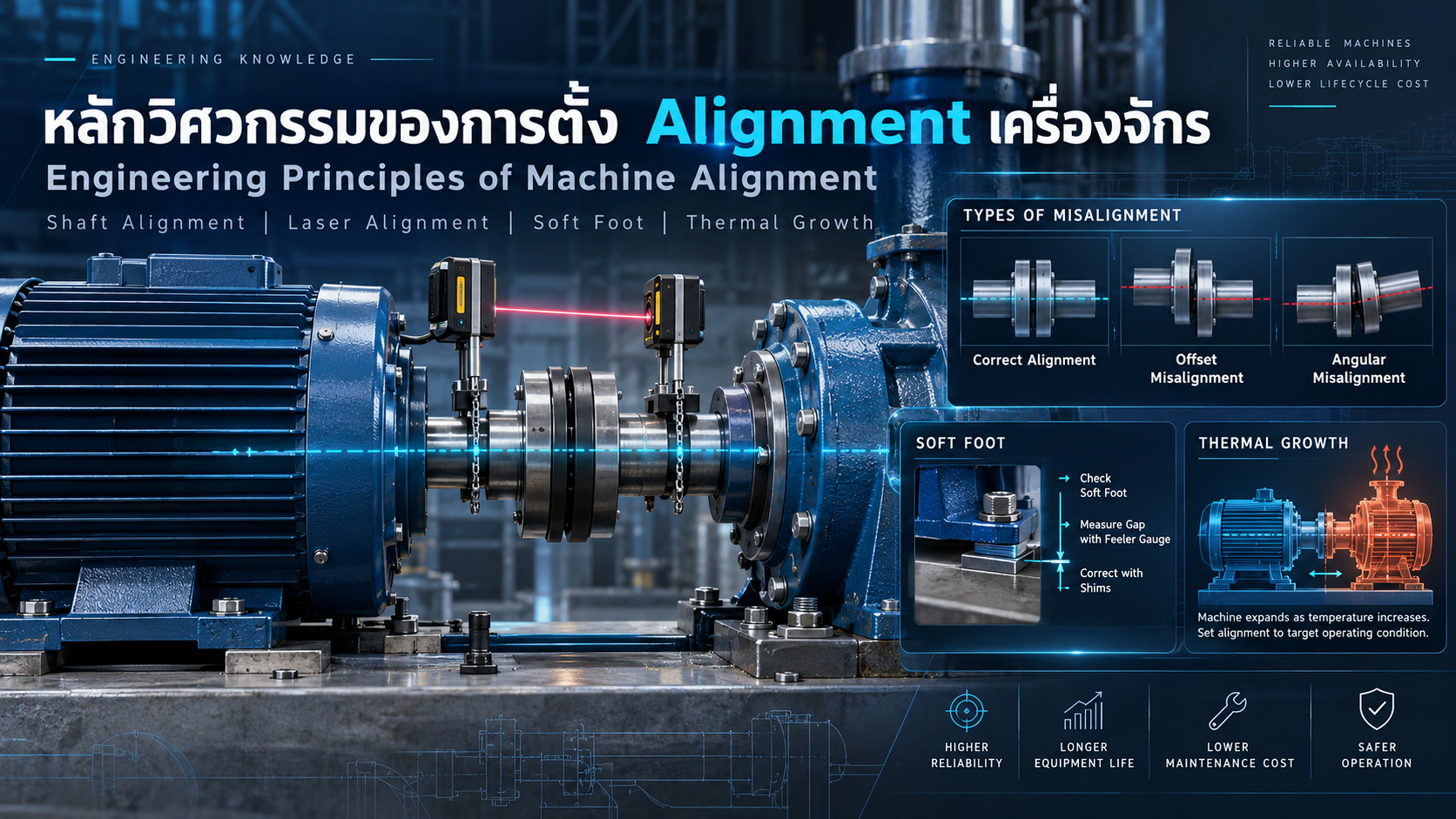
Engineering Principles of Machine Alignment: Methods, Accuracy and Industrial Applications
A Practical Guide to Shaft Alignment, Machine Leveling, Soft Foot, Laser Alignment, Thermal Growth and Precision Machinery Installation
Machine alignment is an essential engineering process in industrial equipment installation, commissioning and maintenance.
Even when machines are manufactured with precision components, incorrect installation or shaft positioning can introduce unwanted mechanical forces that affect performance, reliability and operating life.
Common examples include electric motors connected to pumps, gearboxes driving conveyors, compressors, rotating equipment and precision machinery assemblies.
Misalignment can increase loads on bearings, shafts, couplings and other mechanical components. Depending on the machinery and operating conditions, it may contribute to vibration, excessive heat, premature wear and unplanned downtime.
Understanding the engineering principles of Machine Alignment allows engineers and technicians to establish correct reference positions, identify alignment errors and improve machinery reliability.
This article explains the main types of alignment, measuring instruments, correction methods, thermal effects and practical machine installation procedures.
1. What Is Machine Alignment?
Machine Alignment is the process of measuring and adjusting the geometric relationship between machinery components to meet specified installation and operating requirements.
It may involve correcting shaft centerlines, machine levels, pulley positions, guide rail geometry or other mechanical reference features.
Main Objectives
Establish appropriate geometric relationships
Reduce unnecessary mechanical loading
Minimize alignment-related vibration
Reduce coupling and bearing wear
Improve machinery operating consistency
Support efficient power transmission
Reduce maintenance requirements
Improve machine reliability and service life
Correct alignment does not always mean making every machine surface perfectly horizontal.
The actual objective is to achieve the specified relationship between functional reference features under the relevant operating conditions.
2. Main Types of Industrial Machine Alignment
Shaft Alignment
Shaft Alignment focuses on the relative positions and directions of two rotating shaft centerlines.
Typical applications include:
Electric Motor and Pump
Motor and Gearbox
Compressor and Driver
Motor and Conveyor Drive
Coupled Rotating Machinery
Both angular and offset misalignment must be considered in vertical and horizontal planes.
Machine Leveling
Machine Leveling involves adjusting machinery support points or reference surfaces according to specified geometric requirements.
It is particularly important for machine tools, precision equipment and structures sensitive to base distortion.
A correctly leveled machine is not necessarily correctly shaft-aligned.
Pulley Alignment
Pulley Alignment ensures that drive and driven pulleys are positioned correctly relative to the belt path.
Incorrect alignment can contribute to excessive belt wear, noise, vibration and bearing loads.
Linear Guide Alignment
Linear Guide Alignment involves checking the straightness, parallelism and relative position of rails, guides and motion components.
It is relevant to CNC machines, automated assembly equipment and precision motion systems.
Geometric Alignment
Geometric Alignment evaluates relationships such as straightness, squareness, parallelism and axis positioning.
These checks are especially important in precision machinery and machine tools.
3. Types of Shaft Misalignment
Offset or Parallel Misalignment
Offset Misalignment occurs when two shaft centerlines are parallel but displaced from one another.
For example, a motor shaft may be positioned 0.20 mm higher than the driven shaft while remaining parallel to it.
Angular Misalignment
Angular Misalignment occurs when the shaft centerlines are not parallel and form an angle.
This may occur even when the shaft centers appear close together at the coupling.
Combined Misalignment
In actual machinery, angular and offset errors commonly occur together.
Both must be evaluated to establish proper alignment.
| Misalignment Type | Description |
|---|---|
| Offset | Parallel shaft centerlines with displacement |
| Angular | Shaft centerlines at different angles |
| Combined | Offset and angular errors together |
| Vertical | Alignment error in the vertical plane |
| Horizontal | Alignment error in the horizontal plane |
4. Why Is Proper Shaft Alignment Important?
Incorrect alignment may introduce unwanted loads into the drivetrain.
Possible consequences include:
Bearing Wear: Increased bearing loads may reduce operating life.
Coupling Damage: Flexible elements may experience excessive deformation and wear.
Vibration: Misalignment may contribute to increased mechanical vibration.
Seal Problems: Unwanted shaft motion and loads may affect mechanical seals.
Shaft Stress: Additional bending and reaction forces may occur.
Energy Loss: Mechanical losses may increase under certain conditions.
Downtime: Premature component failures may result in unplanned maintenance.
Flexible couplings can accommodate limited misalignment, but their maximum allowable displacement should not automatically be used as the target for precision machine alignment.
5. Tools Used for Machine Alignment
Precision Spirit Level
Used to measure machine level and surface inclination.
Its resolution and accuracy must be appropriate for the application.
Dial Indicator
Used to measure small positional changes or runout.
Common shaft alignment techniques include:
Rim and Face Method
Reverse Dial Indicator Method
Proper mounting, measurement direction and indicator bracket stability are important for obtaining reliable readings.
Laser Shaft Alignment
Laser systems measure relative shaft positioning and can calculate alignment corrections.
Suitable systems can display:
Vertical Offset
Horizontal Offset
Vertical Angularity
Horizontal Angularity
Front and Rear Foot Corrections
Many systems also support measurement documentation and reporting.
Feeler Gauge
Used for checking gaps and selected soft-foot conditions.
Precision Shims
Used for controlled vertical adjustments beneath machine feet.
Pulley Alignment Tools
Straight edges and dedicated laser tools can help verify pulley positioning.
Laser pulley alignment is particularly useful where more accurate measurements are required.
6. What Is Soft Foot?
Soft Foot is a condition in which machine feet do not rest properly on the supporting base, causing movement or distortion when hold-down bolts are tightened or loosened.
For example, a motor supported by four feet may have one foot that does not contact the base correctly.
When the hold-down bolts are tightened, the motor frame may distort and the shaft alignment readings may change.
Common Causes
Uneven mounting surfaces
Improper shim arrangements
Dirt beneath machine feet
Baseplate distortion
Unequal foot heights
External pipe or structural forces
Basic Inspection Procedure
Isolate machinery according to safety requirements.
Inspect the mounting surfaces.
Install suitable measuring instruments.
Follow the prescribed soft-foot measurement procedure.
Identify affected support points.
Correct the underlying condition using suitable methods.
Repeat measurements before fine alignment.
Soft-foot acceptance criteria depend on the equipment and applicable instructions.
Correcting soft foot is an important prerequisite for reliable shaft alignment.
7. Step-by-Step Machine Alignment Procedure
Step 1: Review Technical Documentation
Check the machine drawings, installation instructions, coupling specifications, alignment tolerances and thermal targets.
Step 2: Inspect the Foundation
Verify the condition of the baseplate, mounting surfaces, anchor bolts and supporting structure.
Step 3: Perform Machine Leveling
Adjust the machine according to its specified reference points and geometric requirements.
Step 4: Check Soft Foot
Identify and correct unsuitable support conditions before precision measurements.
Step 5: Check Shaft and Coupling Runout
Verify that measuring surfaces and rotating components are suitable for accurate alignment.
Step 6: Perform Rough Alignment
Position the machine close to the required alignment before performing precision measurements.
Step 7: Measure Shaft Misalignment
Measure offset and angularity in both horizontal and vertical planes.
Step 8: Correct Vertical Alignment
Adjust machine height and vertical angularity using appropriate shims or specified mechanisms.
Step 9: Correct Horizontal Alignment
Move the adjustable machine horizontally using suitable positioning devices.
Step 10: Tighten Hold-Down Bolts
Tighten fasteners according to the prescribed procedure and verify the alignment again.
Step 11: Check Connected Equipment
Confirm that piping, couplings and other connections do not introduce unacceptable forces or movement.
Step 12: Record and Verify Results
Prepare an alignment report and perform relevant commissioning inspections.
8. Angular Misalignment Calculation
For small angles, angular misalignment can be approximated using the relative change in shaft centerline separation.
θ ≈ Δh / L
Where:
θ = Angular misalignment in radians
Δh = Change in relative centerline separation (mm)
L = Axial distance between measurement locations (mm)
For angularity expressed in millimetres per 100 mm:
Angularity = (Δh / L) × 100
Calculation Example
Assume the measured centerline separation changes by 0.12 mm over an axial distance of 200 mm.
Angularity = (0.12 / 200) × 100
Angularity = 0.06 mm/100 mm
The approximate angular error in radians is:
θ = 0.12 / 200 = 0.0006 rad
Converting to degrees:
θ ≈ 0.0344°
This is a simplified geometrical example.
Actual dial indicator and laser alignment calculations must account for the measurement method, instrument arrangement and reference distances.
The result alone does not establish whether the alignment is acceptable. The applicable machinery tolerance must be known.
9. Understanding Offset Misalignment
Offset Misalignment represents the relative displacement between shaft centerlines at a defined axial reference plane.
For example, a vertical offset of 0.08 mm indicates an 0.08 mm centerline displacement at the specified measurement location.
Accurate alignment analysis may require four values:
Vertical Offset
Horizontal Offset
Vertical Angularity
Horizontal Angularity
Machine-foot corrections depend on the relative distances between the coupling reference plane and the front and rear machine feet.
Therefore, a measured offset of 0.08 mm does not necessarily mean that a shim thickness of 0.08 mm is required.
10. Thermal Growth and Cold Alignment Targets
Machinery temperatures often increase during operation.
Thermal expansion can change the relative positions of rotating shaft centerlines.
This is why some machines require a specific Cold Alignment Target instead of a zero-offset target while stopped.
Linear Thermal Expansion
For a simplified freely expanding component:
ΔL = α × L × ΔT
Where:
ΔL = Thermal expansion (mm)
α = Linear thermal expansion coefficient (1/°C)
L = Original length (mm)
ΔT = Temperature change (°C)
Example
Assume a steel component has:
α = 12 × 10⁻⁶ /°C
L = 400 mm
Temperature increase = 30°C
Then:
ΔL = 12 × 10⁻⁶ × 400 × 30
ΔL = 0.144 mm
The theoretical free thermal expansion is 0.144 mm.
However, this value cannot automatically be used as the required machine-foot shim correction.
Actual shaft centerline movement depends on equipment geometry, support locations, constraints, operating temperatures and the thermal behavior of both connected machines.
Cold alignment targets should be established using OEM specifications, validated calculations or reliable operating measurements.
11. Pipe Strain and External Mechanical Forces
Connected piping can impose loads on pumps and other rotating equipment.
If a pipe flange must be forced into position during assembly, the resulting force can distort the machinery or shift its shaft centerline.
This condition is commonly referred to as Pipe Strain.
Important inspection areas include:
Flange positioning
Pipe support arrangements
Thermal expansion of piping
Equipment nozzle loads
Changes in alignment after piping connection
Piping should be installed according to approved engineering requirements rather than forcing machinery to match incorrectly positioned pipework.
12. How to Determine Alignment Tolerances
There is no single acceptable alignment tolerance for every industrial machine.
Important variables include:
Rotational speed
Coupling design
Shaft arrangement
Operating loads
Thermal growth
Machinery construction
OEM requirements
Required operating reliability
Alignment tolerances may be specified separately for offset and angularity.
The maximum misalignment capacity of a coupling is not necessarily the recommended installation tolerance.
For actual projects, use the approved machinery alignment specifications and manufacturer instructions.
13. Alignment vs. Balancing
Alignment and Balancing are related but different mechanical engineering processes.
Alignment corrects the relative position and direction of machinery components or rotating shaft centerlines.
Balancing adjusts the mass distribution of rotating components to reduce unbalance forces or moments.
A machine may be correctly aligned but still vibrate because of rotor unbalance.
Similarly, a well-balanced machine may still experience problems due to shaft misalignment.
Accurate vibration diagnosis is therefore essential before corrective action.
14. Machine Alignment Inspection and Reporting
Alignment activities should be supported by appropriate documentation.
Alignment Report
A useful report may include:
Equipment identification
Inspection date
Measuring instrument information
Machine dimensions
Initial alignment results (As Found)
Corrected alignment results (As Left)
Applicable tolerances
Soft-foot inspection results
Thermal targets
Operating and measurement conditions
Vibration Monitoring
Vibration measurements can help evaluate machine condition during commissioning and operation.
The ISO 20816 series provides guidance for machinery vibration measurement and evaluation within its applicable scope.
It should not be treated as a direct specification for shaft alignment tolerances.
Temperature Monitoring
Bearing and motor temperatures may provide useful information about machine operating conditions.
Follow-Up Inspection
Machines subject to significant thermal movement or settling may require additional verification according to OEM procedures and site requirements.
15. Relevant Engineering Standards
API RP 686 – Machinery Installation and Installation Design
Provides guidance for machinery installation and precommissioning, particularly in petroleum, chemical and gas industry applications.
ISO 230-1 – Geometric Accuracy of Machine Tools
Provides methods for checking the geometric accuracy of machine tools under no-load or quasi-static conditions.
ISO 20816 – Machine Vibration Measurement and Evaluation
Provides guidelines for measuring and evaluating machinery vibration under defined conditions.
Original Equipment Manufacturer Requirements
Machine manufacturers may specify alignment tolerances, thermal targets, mounting procedures and inspection methods specific to their equipment.
The correct standards and procedures must be selected according to the application.
16. Common Machine Alignment Mistakes
Ignoring Soft Foot
A machine may shift or distort when its mounting bolts are tightened.
Incorrect Thermal Target
A machine aligned at ambient temperature may become misaligned when operating temperatures rise.
Ignoring Angular Misalignment
Correcting only offset may leave the shafts at an undesirable angle.
Using Coupling Surfaces as Unverified References
Coupling runout or unsuitable contact surfaces can distort measurement results.
Ignoring Pipe Strain
Piping forces may change the alignment after installation.
Not Rechecking After Bolt Tightening
Machine movement during tightening may invalidate previous readings.
Applying One Tolerance to Every Machine
Different equipment designs require different acceptance criteria.
Failing to Document Results
Without As Found and As Left data, future troubleshooting becomes more difficult.
17. Frequently Asked Questions
What Is Machine Alignment?
Machine Alignment is the process of measuring and adjusting machinery geometry so that interacting components meet specified positional and directional requirements.
What Is the Difference Between Shaft Alignment and Machine Leveling?
Shaft Alignment focuses on the relative position of rotating shaft centerlines. Machine Leveling focuses on the orientation and geometric condition of machine reference surfaces.
Is Shaft Alignment Necessary with Flexible Couplings?
Generally, yes. Flexible couplings have defined misalignment capabilities, but excessive misalignment may reduce operational reliability.
Is Laser Alignment Better Than Dial Indicator Alignment?
Laser systems can simplify measurement, correction and documentation. Dial indicators can also provide accurate results when used correctly.
Why Is Soft Foot Important?
Soft foot can cause machine frame distortion or movement during bolt tightening, affecting alignment accuracy.
Should All Machines Be Perfectly Aligned When Cold?
No. Some machines require defined cold offsets to compensate for thermal movement during operation.
Can Vibration Confirm Shaft Misalignment?
Vibration can provide diagnostic information, but vibration alone does not definitively establish shaft misalignment.
18. Conclusion
Machine Alignment is a fundamental engineering process for reliable industrial machinery installation and maintenance.
Correct shaft alignment, machine leveling, soft-foot correction and thermal movement evaluation help reduce unnecessary mechanical loading and improve equipment reliability.
Modern tools such as Laser Shaft Alignment systems support accurate measurements and efficient adjustments, but successful alignment still depends on sound engineering practices and appropriate installation conditions.
Documenting alignment results and verifying machinery under relevant operating conditions are important parts of long-term asset reliability.
Good machine alignment is not simply achieving zero readings. It is achieving the correct geometric relationship for reliable machine operation under the specified working conditions.
AC DESIGN AND DEVELOPMENT – Industrial Machinery & Engineering Solutions
AC DESIGN AND DEVELOPMENT CO., LTD. provides customized industrial engineering and manufacturing solutions.
Our services include:
Automation Machine Design and Manufacturing
Custom Jig & Fixture
Conveyor Systems
Machine Parts Manufacturing
Industrial Steel Structures
Custom Engineering Solutions
Our engineering approach focuses on suitable mechanical design, component selection, dimensional accuracy and practical manufacturing solutions.
Engineering and Industrial Machinery Solutions Across Thailand
Website: https://acdesignanddevelopment.com/
Tel: +66 82-210-0792
Technical Disclaimer: This article is intended for educational purposes. Actual machinery alignment must follow approved OEM procedures, equipment-specific tolerances, suitable measurement methods and applicable safety requirements.