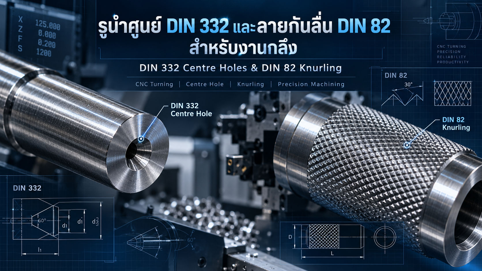
DIN 332 Centre Holes and DIN 82 Knurling: Essential Standards for Lathe Machining
A Practical Guide to Centre Hole Forms, Knurling Profiles, Engineering Drawing Designations and CNC Turning Applications
Precision turning involves more than controlling the diameter, length and dimensional tolerances of mechanical components.
Small engineering features can play important roles in workpiece support, machining accuracy, assembly quality and product functionality.
Two commonly specified features in turning drawings are centre holes and knurled surfaces.
Centre holes provide reference and support surfaces for machining operations between centres or with tailstock support.
Knurling produces controlled surface patterns for improved grip and selected mechanical assembly applications.
The standards commonly referenced for these features include:
DIN 332-1: 60-degree centre holes
DIN 82: Knurling profiles on workpieces
This article explains their functions, classifications, drawing designations, manufacturing methods and practical considerations for manual and CNC lathe operations.
1. What Is DIN 332?
DIN 332 is a group of standards addressing centre holes used in mechanical engineering.
DIN 332-1:1986-04 specifies unthreaded 60-degree centre holes for general engineering applications.
Centre holes are typically manufactured at the ends of cylindrical workpieces to provide support for lathe centres.
Main Functions of Centre Holes
Supporting long workpieces during turning
Helping control workpiece alignment
Supporting machining between centres
Providing repeatable reference locations
Supporting precision grinding operations
Reducing unwanted workpiece deflection when properly applied
Correct centre hole geometry is important because damaged or incorrectly manufactured centre holes can negatively affect machining accuracy and workpiece support.
2. DIN 332 Centre Hole Types
DIN 332-1 identifies four principal centre hole forms: A, B, C and R.
Form A – Straight Form
Form A is a conventional 60-degree centre hole without an additional protective chamfer.
It has a relatively simple configuration and is commonly used for general turning applications.
Form B – Conical Protective Chamfer
Form B includes a conical protective chamfer at the entrance of the centre hole.
The protective feature helps reduce the risk of damage to the functional centre-contact surface during appropriate handling and use.
Form C – Truncated Protective Chamfer
Form C includes a truncated protective chamfer with geometry defined by the standard.
Producing this configuration may require additional machining operations or multiple tools.
Form R – Radius Form
Form R uses a radius-form contact geometry rather than a conventional straight conical configuration throughout the contact profile.
It must be produced using a suitable method and dimensional specifications for the required radius form.
Comparison Table
| Form | Configuration | Main Feature |
|---|---|---|
| A | Straight centre hole | No protective chamfer |
| B | Conical protective chamfer | Protected entrance geometry |
| C | Truncated protective chamfer | Special protective configuration |
| R | Radius form | Curved contact geometry |
The appropriate form should be selected based on the workpiece, centre support conditions, machining process and engineering drawing requirements.
3. How to Read DIN 332 Centre Hole Designations
Consider the following example:
Centre Hole DIN 332 – A 2 × 4.25
The designation identifies:
DIN 332: Centre hole standard
A: Form A
2: Centre hole diameter d1, in millimetres
4.25: Conical opening diameter d2, in millimetres
The dimensions identify a standardized centre hole size.
Importantly, 4.25 mm is not automatically the drilling depth.
The required depth and full geometry must be verified using the applicable standard.
4. DIN 332 vs. DIN 333
DIN 332 specifies the centre hole geometry on the workpiece.
DIN 333 specifies centre drills used to manufacture appropriate centre hole forms.
For example, a centre hole specified as DIN 332 Form B requires a manufacturing process and tool combination capable of producing the specified protective chamfer.
Not all centre drill types are interchangeable.
5. How to Machine Centre Holes on a Lathe
A general centre hole machining procedure includes:
Review the engineering drawing and identify the centre hole form.
Secure the workpiece correctly in the lathe.
Face the workpiece end if required.
Select a suitable centre drill.
Align the cutting tool with the spindle axis.
Set the appropriate spindle speed and feed.
Machine the centre hole according to the required geometry.
Inspect the centre hole and remove unwanted burrs.
Verify suitability for tailstock support or subsequent machining operations.
Important Considerations
Select the centre hole size according to actual loading and machining requirements.
Avoid excessive centre pressure.
Verify correct contact between the centre and the supporting surface.
Use suitable lubrication where required.
Inspect centre holes for damage before reuse.
A correctly manufactured centre hole can improve workholding consistency, but it does not independently guarantee machining accuracy.
6. What Is DIN 82?
DIN 82 is a German standard defining knurling profiles used on manufactured components.
Knurling is a manufacturing process that creates regular grooves or raised patterns on a workpiece surface.
Knurled surfaces are commonly used to improve hand grip or provide selected mechanical retention features.
Typical applications include:
Hand knobs
Machine handles
Adjustment screws
Thumb screws
Grip sleeves
Hand-operated locking components
Selected press-fit pins and inserts
The required surface profile should be clearly specified in the engineering drawing.
7. Types of DIN 82 Knurling Profiles
RAA – Straight Knurl
RAA produces straight grooves parallel to the workpiece axis.
It is commonly used on cylindrical gripping surfaces.
RBL – Left-Hand Knurl
RBL produces left-hand inclined grooves, commonly using a standardized 30-degree spiral angle.
RBR – Right-Hand Knurl
RBR produces right-hand inclined grooves.
Its orientation is opposite to that of RBL.
RGE – Diamond Knurl with Raised Points
RGE produces a left-right crossed diamond pattern with raised points.
It is widely used for hand-operated mechanical components.
RGV – Diamond Knurl with Indented Points
RGV produces a crossed diamond pattern with indented points.
RKE – Cross Knurl with Raised Points
RKE produces a cross-hatched knurling pattern with raised points and a 90-degree crossing arrangement.
RKV – Cross Knurl with Indented Points
RKV produces an indented cross-hatched knurling pattern.
Summary Table
| Code | Knurling Profile |
|---|---|
| RAA | Straight knurl |
| RBL | Left-hand knurl |
| RBR | Right-hand knurl |
| RGE | Diamond knurl, raised points |
| RGV | Diamond knurl, indented points |
| RKE | Cross knurl, raised points |
| RKV | Cross knurl, indented points |
The workpiece profile designation is not necessarily identical to the profile marking on the knurling wheel.
Tool selection depends on the required finished profile and manufacturing process.
8. How to Read DIN 82 Knurling Designations
Consider the example:
Knurl RGE 08 DIN 82
This designation identifies:
Knurl: Knurled surface requirement
RGE: Raised diamond knurl profile
08: Pitch of 0.8 mm
DIN 82: Knurling standard
What Is Knurling Pitch?
Knurling pitch is the spacing between corresponding profile features, measured according to the relevant profile definition.
Common tool pitches include:
0.5 mm
0.6 mm
0.8 mm
1.0 mm
1.2 mm
1.6 mm
A smaller pitch generally produces a finer pattern.
A larger pitch generally produces a coarser surface pattern.
The correct pitch depends on workpiece diameter, material, machining process and grip requirements.
9. Form Knurling vs. Cut Knurling
Two manufacturing methods are commonly used for producing knurled surfaces.
Form Knurling
Form knurling uses pressure from knurling wheels to plastically deform the workpiece surface.
The material is displaced rather than removed as chips.
Advantages
Widely available tooling
Suitable for many ductile materials
Can produce regular knurled surfaces
Limitations
Generates significant forming loads
Can increase the finished outside diameter
May deform thin or slender workpieces
Requires correct wheel alignment and pitch selection
Cut Knurling
Cut knurling uses specially designed cutting tools to remove material and create the required pattern.
Advantages
Can reduce forming loads in suitable applications
Useful for some slender workpieces
Provides a machining alternative to material displacement
Limitations
Requires suitable cutting tools and holders
Produces chips
Requires appropriate cutting conditions and lubrication
Not every profile is supported by every tool system
10. Does Knurling Change the Workpiece Diameter?
An important characteristic of form knurling is that the outer diameter may increase as material is displaced into the raised profile.
For example, a workpiece initially turned to Ø20.00 mm may have a larger crest diameter after form knurling.
The amount of diameter growth depends on:
Knurling profile
Pitch
Material properties
Initial workpiece diameter
Forming depth
Wheel geometry
Tool alignment and process conditions
A pitch of 0.8 mm does not mean the outside diameter will increase by exactly 0.8 mm.
When the finished knurled diameter affects assembly, its dimensional limits should be specified and verified through machining trials.
11. Common Knurling Problems
Double Knurling
The knurling wheel may fail to track the existing pattern correctly, producing unwanted overlapping or excessively fine grooves.
Incomplete Profile
Insufficient tool penetration may prevent the required pattern from forming completely.
Pattern Distortion
Incorrect alignment, process parameters or unsuitable tool setup may produce uneven profiles.
Workpiece Deflection
High radial forming loads can bend slender workpieces.
Knurling Wheel Wear
Unsuitable loading, lubrication or material conditions may accelerate tool wear.
Incorrect Final Diameter
Failure to account for material displacement may result in out-of-tolerance parts.
12. Using DIN 332 and DIN 82 Together
DIN 332 and DIN 82 serve different purposes but may both appear in the engineering drawing of one turned component.
Consider a custom adjustment shaft with a hand-operated gripping section.
The design may specify:
Centre Hole: DIN 332 Form A or Form B, depending on the support and machining requirements.
Knurling: DIN 82 RGE with 0.8 mm pitch on the gripping section.
Shaft Dimensions: Appropriate dimensional tolerances and surface finish requirements.
This combination allows the manufacturer to identify the workholding reference requirements and the finished gripping pattern.
13. Best Practices for Engineering Drawings
DIN 332 Centre Hole Information
Specify:
Centre hole form
Standard size
Quantity and location
Whether the centre hole remains on the finished workpiece
Additional functional requirements
DIN 82 Knurling Information
Specify:
Finished knurling profile
Pitch
Special spiral or profile angles when applicable
Knurled length and location
Finished diameter requirements
Relevant dimensional tolerances
Clear drawing specifications reduce manufacturing interpretation errors and improve part consistency.
14. Frequently Asked Questions
What Is DIN 332 Used For?
DIN 332-1 specifies 60-degree centre hole geometry for general mechanical engineering applications.
What Is the Difference Between DIN 332 and DIN 333?
DIN 332 defines centre holes on workpieces, while DIN 333 defines related centre drills.
What Is DIN 82?
DIN 82 specifies knurling profiles such as straight, inclined, diamond and cross-hatched patterns.
What Does RAA Mean?
RAA identifies a knurling profile with grooves parallel to the workpiece axis.
What Does RGE 08 Mean?
RGE identifies a raised diamond knurling pattern, while 08 indicates a pitch of 0.8 mm.
Can DIN 82 Knurling Be Produced on a CNC Lathe?
Yes. A CNC lathe can produce specified knurling profiles using appropriate tooling and machining parameters.
Does Form Knurling Increase Diameter?
It can increase the outside diameter because material is displaced during the forming operation.
15. Conclusion
DIN 332 and DIN 82 are important technical references for turning operations and precision machine component manufacturing.
DIN 332-1 specifies centre hole forms that support accurate workholding and machining between centres.
DIN 82 defines knurling profiles used for gripping surfaces and selected assembly applications.
Understanding these standards helps engineers communicate manufacturing requirements, select appropriate tooling and improve dimensional consistency.
Correct engineering drawings should clearly specify centre hole forms, knurling profiles, pitch, dimensions and relevant tolerances.
Small machining details can have a significant impact on the quality, reliability and functionality of industrial machine components.
AC DESIGN AND DEVELOPMENT – Precision Engineering & Machine Parts Solutions
AC DESIGN AND DEVELOPMENT CO., LTD. provides custom mechanical engineering and industrial manufacturing solutions.
Our services include:
Automation Machine Design and Manufacturing
Custom Machine Parts
Jig & Fixture Design and Manufacturing
CNC Machining Parts
Conveyor Systems
Industrial Steel Structures
Custom Engineering Solutions
We focus on practical engineering designs and manufacturing solutions that support dimensional accuracy, reliable machine operation and production efficiency.
Engineering and Manufacturing Services Across Thailand
Website: https://acdesignanddevelopment.com/
Tel: +66 82-210-0792
Technical Disclaimer: This article is provided for engineering education. Actual manufacturing requirements must be verified against the applicable standards, controlled drawings, tooling specifications and machine safety procedures.