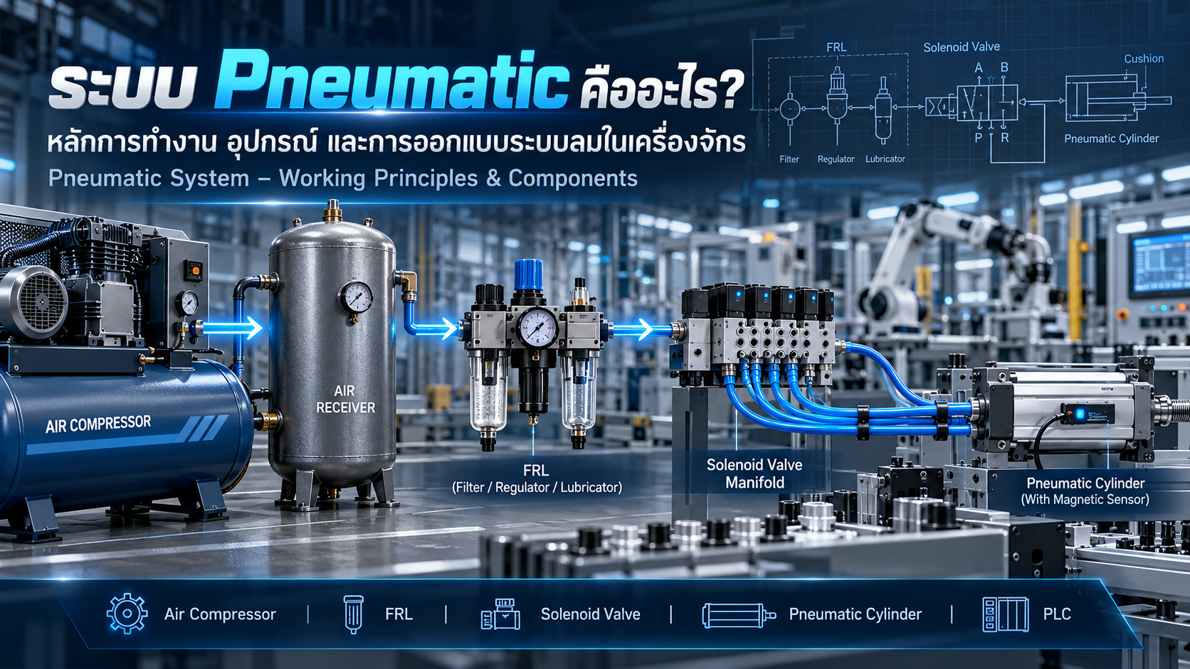
Pneumatic System Explained: Working Principles, Components, Circuit Design and Industrial Applications
A Complete Engineering Guide to Air Compressors, Air Preparation, FRL Units, Solenoid Valves, Pneumatic Cylinders, Force Calculations and PLC Automation
Pneumatic systems are widely used in industrial machinery and factory automation.
From pneumatic clamping devices and conveyor stoppers to automated assembly machines and pick-and-place mechanisms, compressed air provides a practical source of mechanical power for many manufacturing applications.
A pneumatic system converts compressed-air energy into mechanical force and motion through a combination of air supply equipment, valves, actuators and control devices.
However, an industrial pneumatic system is more than a pneumatic cylinder connected to a solenoid valve.
Reliable operation requires appropriate compressed-air quality, pressure regulation, flow control, correctly sized components, feedback sensors and suitable safety measures.
This article explains the major pneumatic system components, how they work together, basic engineering calculations and important considerations for industrial automation design.
1. What Is a Pneumatic System?
A Pneumatic System uses pressurized gas, typically compressed air, to transmit energy and perform mechanical operations.
Compressed air is delivered through tubing, valves and pressure-control devices to pneumatic actuators.
The actuators convert pneumatic energy into linear or rotary motion.
Common Applications
Workpiece clamping
Conveyor stoppers
Automatic part pushing
Pneumatic gripping
Machine door actuation
Component positioning
Packaging machinery
Automated assembly
Air-blow operations
Pneumatically generated vacuum
Advantages
Relatively simple mechanical construction
Fast repetitive movement in suitable applications
Wide availability of industrial components
Convenient PLC integration
Flexible installation arrangements
Suitable for many two-position machine operations
Limitations
Compressed air has significant elasticity
Available force depends on operating pressure
Air leakage increases energy consumption
Air quality requires maintenance
Continuous positioning may require specialized equipment
Stored compressed-air energy can create safety hazards
2. How Does a Pneumatic System Work?
A typical pneumatic system operates through the following stages.
Step 1: Compressed Air Generation
An air compressor draws atmospheric air and raises its pressure.
Step 2: Air Storage
Compressed air may be stored in a receiver tank to support system demand.
Step 3: Air Treatment
Dryers, filters and separators improve compressed-air quality.
Step 4: Pressure Regulation
A pressure regulator establishes the required downstream working pressure.
Step 5: Directional Control
A directional control valve selects the airflow path.
Step 6: Actuation
A pneumatic cylinder or actuator converts the supplied pressure into mechanical force and movement.
Step 7: Exhaust
Air from the opposite actuator chamber is exhausted through the designed flow path.
Step 8: Feedback
Sensors report position or pressure information to the controller.
The controller uses these signals to coordinate the next machine operation.
3. Major Pneumatic System Components
Industrial pneumatic components can be divided into several groups.
Air Supply
Air Compressor
Air Receiver Tank
Aftercooler
Pressure Gauge
Pressure Relief Device
Air Preparation
Air Dryer
Water Separator
Air Filter
Pressure Regulator
Lubricator
Filter Regulator / FRL Unit
Airflow and Directional Control
Solenoid Valve
Directional Control Valve
Speed Controller
Flow Control Valve
Check Valve
Quick Exhaust Valve
Shut-Off Valve
Soft-Start Valve
Pneumatic Actuators
Single-Acting Cylinder
Double-Acting Cylinder
Compact Cylinder
Guided Cylinder
Rodless Cylinder
Rotary Actuator
Pneumatic Gripper
Monitoring and Connections
Pressure Sensor
Pressure Switch
Cylinder Auto Switch
Pneumatic Tubing
Push-In Fittings
Valve Manifold
Exhaust Silencer
Not every pneumatic machine requires all these components.
The final configuration depends on operating requirements and risk assessment.
4. Air Compressor
An Air Compressor provides the compressed-air supply for a pneumatic system.
Common technologies include:
Reciprocating Compressor
Uses one or more pistons to compress air.
Rotary Screw Compressor
Uses rotating screw elements and is widely used in industrial compressed-air installations.
Scroll Compressor
Uses a scroll compression mechanism and may be selected for applications requiring specific noise or air-quality characteristics.
Compressor Selection
Important specifications include:
Operating pressure
Free Air Delivery (FAD)
Total air consumption
Peak air demand
Duty cycle
Energy efficiency
Maintenance requirements
The compressor must be selected based on the required flow at the operating pressure, not simply the maximum pressure rating.
5. Air Receiver Tank
An Air Receiver Tank stores compressed air and supports pressure and flow management.
Its functions may include:
Short-term storage
Supporting peak air demand
Reducing compressor cycling in certain systems
Helping manage supply pressure fluctuations
Supporting condensate separation arrangements
Receiver tanks require appropriate pressure-protection devices, inspection and maintenance.
They must comply with applicable pressure-equipment requirements.
6. Air Dryer and Water Separator
Compressed air can contain water vapor that condenses as operating conditions change.
Excessive moisture can affect pneumatic valves, actuators and other components.
Water Separator
Removes liquid water droplets or condensate within its operating capability.
Air Dryer
Reduces moisture content to achieve an appropriate pressure dew point.
Common technologies include:
Refrigerated Air Dryer
Adsorption Dryer
Membrane Dryer
A water separator does not replace a dryer in applications requiring a specific low pressure dew point.
Air preparation equipment should be selected according to the quality required at the point of use.
7. What Is an FRL Unit?
FRL stands for:
F – Filter
Removes specified contaminants from compressed air.
R – Regulator
Controls downstream air pressure.
L – Lubricator
Introduces oil mist when required by the connected pneumatic equipment.
Is a Lubricator Always Necessary?
No.
Many modern pneumatic components are designed for operation without externally introduced oil mist.
Lubrication should only be added when specified by the equipment manufacturer and appropriate for the application.
Additional Air Preparation Devices
Air preparation assemblies may include:
Pressure Gauges
Shut-Off Valves
Soft-Start Valves
Fine Filters
Pressure Sensors
Air Distribution Modules
Proper selection requires consideration of airflow capacity, pressure drop and compressed-air quality.
8. Solenoid and Directional Control Valves
A Solenoid Valve uses an electrical signal to control the valve mechanism.
Directional control valves determine which pneumatic passages are connected.
2/2-Way Valve
Two ports and two switching positions.
Often used for basic opening or closing of an airflow path.
3/2-Way Valve
Three ports and two positions.
Commonly used for single-acting cylinders and pneumatic signal functions.
5/2-Way Valve
Five ports and two positions.
Commonly used to control double-acting cylinders.
5/3-Way Valve
Five ports and three positions.
Provides an additional center position.
Common center configurations include:
Closed Center
Exhaust Center
Pressure Center
Each configuration produces different actuator behavior.
A closed-center valve must not automatically be considered a safe load-holding device, because leakage and external forces may still cause movement.
9. Understanding Pneumatic Valve Ports
Typical 5/2 directional control valve port designations are:
| Port | Function |
|---|---|
| 1 (P) | Pressure Supply |
| 2 (A) | Working Port A |
| 4 (B) | Working Port B |
| 3 (R) | Exhaust |
| 5 (S) | Exhaust |
Depending on the valve position, supply pressure is connected to one actuator chamber while the opposite chamber is connected to exhaust.
The resulting extension or retraction depends on the actual tubing arrangement and cylinder configuration.
The manufacturer's pneumatic symbol and connection diagram must be verified.
10. Pneumatic Cylinders
A pneumatic cylinder converts compressed-air pressure into linear mechanical force and movement.
Single-Acting Cylinder
Uses pressure to produce motion in one direction.
The return movement is produced by a spring or external force.
Double-Acting Cylinder
Uses compressed air to control both extension and retraction.
Compact Cylinder
Provides a short overall construction for limited installation spaces.
Guided Cylinder
Includes guiding elements designed to support specified side loads and moments.
Rodless Cylinder
Transfers linear motion without the conventional external piston rod arrangement.
Rotary Actuator
Produces angular movement.
Pneumatic Gripper
Uses pneumatic force to operate a mechanical gripping mechanism.
The selected actuator must satisfy the required force, stroke, speed, load and service-life conditions.
11. Pneumatic Cylinder Force Calculation
The basic theoretical force equation is:
F = P × A
For a double-acting cylinder with one piston rod:
Extension Force
F_extend = P × πD² / 4
Retraction Force
F_retract = P × π(D² − d²) / 4
Where:
F = Theoretical force (N)
P = Gauge pressure (MPa)
D = Cylinder bore (mm)
d = Piston rod diameter (mm)
Example
Assume:
Bore Diameter = 32 mm
Rod Diameter = 12 mm
Pressure = 0.6 MPa
Extension piston area:
A_extend ≈ 804.25 mm²
Extension force:
F_extend ≈ 482.55 N
Retraction annular area:
A_retract ≈ 691.15 mm²
Retraction force:
F_retract ≈ 414.69 N
Actual available force is affected by friction, exhaust back pressure, pressure losses and mechanical loading.
The result is a theoretical calculation rather than a guaranteed cylinder output.
12. Pneumatic Air Consumption Calculation
Air consumption is important when selecting compressors, valves and tubing.
For a double-acting cylinder:
V_extend = πD²S / 4
V_retract = π(D² − d²)S / 4
Where:
V = Cylinder chamber volume
S = Stroke
D = Bore diameter
d = Rod diameter
Example
Assume:
Bore = 32 mm
Rod = 12 mm
Stroke = 100 mm
Working Pressure = 0.6 MPa Gauge
20 complete extension/retraction cycles per minute
The chamber volumes are approximately:
Extension Volume = 0.0804 L
Retraction Volume = 0.0691 L
Total chamber filling volume per cycle:
0.1495 L
For a simplified reference conversion using:
Atmospheric pressure = 0.1 MPa absolute
Operating pressure = 0.7 MPa absolute
Equal reference temperature
Pressure ratio:
0.7 / 0.1 = 7
Equivalent atmospheric-reference air volume per cycle:
0.1495 × 7 ≈ 1.047 L
At 20 cycles per minute:
Air Consumption ≈ 20.94 L/min
This calculation excludes air leakage, additional tubing volumes, valve losses and other compressed-air consumers.
The entire machine's air requirements must be assessed before selecting the compressed-air supply system.
13. Speed Controllers and Flow Control
Pneumatic cylinder speed can be adjusted by controlling airflow.
Meter-In Control
Restricts the air entering the actuator chamber.
Meter-Out Control
Restricts air leaving the actuator chamber.
Meter-out control is commonly used for double-acting pneumatic cylinders because exhaust restriction can provide useful motion resistance.
However, the appropriate method depends on the load and application.
Important Considerations
Flow controller orientation
Valve flow capacity
Cylinder speed
Load inertia
Pneumatic cushioning
Exhaust pressure
Pressure variation
Speed controllers must not be assumed to provide a safety-rated load-holding function.
14. Other Important Pneumatic Components
Check Valve
Permits flow in a specified direction and restricts reverse flow.
Pilot-Operated Check Valve
Uses pilot pressure to control reverse flow.
It may be used in selected load-retention arrangements, subject to appropriate design and verification.
Quick Exhaust Valve
Provides a short exhaust path near the actuator to reduce exhaust restriction in suitable applications.
Pressure Relief Valve
Protects designated parts of a system against excessive pressure according to its design and rating.
Pressure Reducing Valve
Establishes a lower pressure for a specific circuit.
Soft-Start Valve
Controls how pressure is introduced into a pneumatic circuit.
Shut-Off / Dump Valve
Isolates or exhausts compressed air according to its intended function.
Silencer
Reduces noise from exhaust airflow.
Manifold
Provides a common mounting and air distribution arrangement for multiple valves.
Each component must be selected according to pressure, flow, operating conditions and safety requirements.
15. Pneumatic Tubing and Fittings
Pneumatic tubing connects the different components within a compressed-air circuit.
Typical tubing materials include:
Polyurethane
Polyamide
PTFE and specialized materials
Common fittings include:
Straight Fittings
Elbow Fittings
Tee Fittings
Reducers
Bulkhead Fittings
Push-In Connectors
Selection Factors
Working pressure
Flow rate
Internal and external diameters
Temperature range
Chemical compatibility
Minimum bend radius
Mechanical protection
Undersized tubing and fittings can cause excessive pressure drop and reduce actuator performance.
16. Sensors in Pneumatic Systems
Pressure Switch
Provides a switching signal when a defined pressure condition is reached.
Pressure Sensor
Provides pressure measurement data.
Cylinder Auto Switch
Detects the magnetic field of a compatible cylinder piston.
Flow Sensor
Measures airflow under specified conditions.
Practical Example
A PLC commands a cylinder to extend.
If the extended-position signal is not received within the specified time, the controller may generate a fault such as:
Cylinder Extend Timeout
The system must then respond according to its programmed sequence and assessed safety requirements.
Cylinder position feedback does not automatically establish that a workpiece is securely clamped with adequate force.
17. Understanding Pneumatic Circuit Diagrams
Pneumatic circuit diagrams describe components and their functional connections using standardized graphical symbols.
ISO 1219-1 provides a system for fluid power graphical symbols.
Common diagram elements include:
Compressed-air supply
Filters
Regulators
Directional valves
Flow controllers
Check valves
Cylinders
Exhaust silencers
Sensors
Understanding a pneumatic schematic helps engineers identify airflow paths, actuator behavior, control signals and possible stored-energy conditions.
18. PLC Control of a Pneumatic Cylinder
A basic PLC-controlled double-acting cylinder system may include:
PLC Controller
5/2 Directional Control Valve
Double-Acting Cylinder
Cylinder Position Sensors
Pressure Monitoring
Speed Controllers
Example Operating Sequence
Step 1 – Ready
Verify that the machine is ready to operate.
Step 2 – Extend Command
Command the valve to supply air for cylinder extension.
Step 3 – Extension
The cylinder moves toward the required position.
Step 4 – Position Confirmation
The extended-position sensor confirms movement.
Step 5 – Manufacturing Process
The machine performs the required production operation.
Step 6 – Retract Command
The valve directs air for retraction.
Step 7 – Retraction Confirmation
The retracted-position sensor confirms that the cylinder has returned.
Step 8 – Cycle Complete
The controller allows the next operating cycle.
The actual control logic depends on valve type, feedback arrangements and safety requirements.
19. Pneumatic vs. Hydraulic Systems
| Feature | Pneumatic | Hydraulic |
|---|---|---|
| Working Medium | Compressed Air | Pressurized Liquid |
| Compressibility | Relatively High | Relatively Low |
| Common Applications | Clamping, Pushing, Handling | Pressing, Heavy Loads |
| Force Capability | Suitable for many low-to-medium force tasks | Suitable for high-force tasks |
| Maintenance | Air quality, valves and seals | Fluid, pumps, valves and seals |
| Main Considerations | Air consumption and compressibility | Fluid management and high pressure |
Both systems can be integrated into industrial automation.
Selection depends on force requirements, accuracy, speed, environment and total cost.
20. Pneumatic System Energy Efficiency
Compressed air requires electrical energy for generation and processing.
Improving pneumatic system efficiency can reduce operating costs.
Recommended practices include:
Detecting and repairing air leaks
Using only the pressure necessary for reliable operation
Selecting appropriately sized cylinders
Avoiding unnecessarily long tubing
Minimizing excessive pressure drops
Using suitable flow-control components
Optimizing air-blow functions
Monitoring compressed-air consumption
Evaluating vacuum ejector air usage
Energy-saving measures must not compromise required safety functions or machine performance.
21. Pneumatic System Safety
Pneumatic systems contain pressurized energy and can generate hazardous mechanical movement.
Important risks include:
Unexpected actuator movement
Crushing and pinching
Falling suspended loads
Stored pressure
Hose or fitting failure
Uncontrolled exhaust
Unexpected restart
Potential protective measures include:
Machinery risk assessment
Suitable isolation and lockout procedures
Stored-energy management
Appropriate guarding
Safe pneumatic control functions
Load-retention measures
Pressure monitoring
Correctly designed emergency stop arrangements
Regular inspection and maintenance
Emergency stopping must not automatically cause suspended loads to be released.
A safe response must be established through the machine risk assessment and verified safety design.
22. Relevant Engineering Standards
ISO 4414:2010
Provides general rules and safety requirements for pneumatic fluid power systems and components used in machinery.
ISO 8573-1:2010
Defines compressed-air purity classes for particles, water and oil.
ISO 1219-1:2012
Provides graphical symbol requirements for fluid power components and circuit diagrams.
ISO 15552:2018
Establishes applicable basic and mounting dimensions for specified pneumatic cylinders.
ISO 12100:2010
Provides principles for machinery risk assessment and risk reduction.
Additional standards may be necessary for electrical control, functional safety, compressed-air installations and other specific applications.
23. Common Pneumatic System Problems
Cylinder Does Not Extend
Possible causes include insufficient pressure, valve faults, blocked tubing or excessive mechanical resistance.
Cylinder Moves Too Slowly
Check flow controls, tubing diameter, valve capacity and pressure drop.
Cylinder Does Not Retract
Inspect valve operation, supply pressure, exhaust paths and mechanical loading.
Insufficient Cylinder Force
Check actual working pressure, effective piston area and applied loads.
Excessive Impact at End of Stroke
Review speed, cushioning and moving mass.
Water Accumulation
Inspect dryers, filters, separators and condensate drains.
High Air Consumption
Check for leakage and unnecessary continuous compressed-air use.
Unexpected Cylinder Movement
Evaluate valve states, stored pressure, external forces and load-retention requirements.
24. Industrial Applications
Jig & Fixture
Pneumatic clamps can secure workpieces during production.
Conveyor Systems
Pneumatic actuators can stop, position, push or divert products.
Automated Assembly
Cylinders and pneumatic grippers operate mechanisms within automatic production machines.
Pick and Place
Pneumatic grippers and actuators can handle appropriate components.
Packaging Machinery
Pneumatic systems support product positioning, pushing and selected packaging operations.
Welding Fixtures
Pneumatic clamps may hold components during welding, subject to load and environmental requirements.
Inspection Equipment
Pneumatic devices can position test pieces and operate rejection mechanisms.
25. Frequently Asked Questions
What Is a Pneumatic System?
A pneumatic system uses compressed air to generate and control mechanical force or movement.
What Are the Main Components?
Typical components include compressors, receivers, dryers, filters, regulators, valves, cylinders, sensors, tubing and fittings.
What Does FRL Stand For?
Filter, Regulator and Lubricator.
What Is the Difference Between 3/2 and 5/2 Valves?
A 3/2 valve has three ports and two positions, while a 5/2 valve has five ports and two positions.
How Much Force Can a Pneumatic Cylinder Produce?
Theoretical force depends on pressure and effective piston area.
For example, a 32 mm bore cylinder at 0.6 MPa generates approximately 482.55 N of theoretical extension force.
Can Pneumatic Systems Work with PLCs?
Yes. PLCs commonly control solenoid valves and monitor actuator feedback.
Are Lubricators Always Required?
No. Lubrication requirements depend on the selected pneumatic equipment.
Can Pneumatic Cylinders Lift Heavy Loads?
Yes, when correctly rated and designed. Suspended loads require suitable protection against uncontrolled movement or pressure loss.
26. Conclusion
Pneumatic systems are important technologies in industrial automation and machinery design.
They convert compressed-air energy into controlled mechanical movement through a combination of air supply systems, pressure regulators, valves and actuators.
Reliable operation depends on suitable air quality, component selection, pressure and flow management, PLC integration and mechanical design.
Engineers must consider cylinder force, stroke, cycle time, air consumption, safety and maintenance throughout the design process.
A well-designed pneumatic system is not simply one that operates at the highest air pressure. It is a system that provides reliable motion, appropriate force, efficient air consumption and safe operation under its intended working conditions.
AC DESIGN AND DEVELOPMENT – Pneumatic & Industrial Automation Solutions
AC DESIGN AND DEVELOPMENT CO., LTD. provides customized industrial engineering and machinery manufacturing solutions.
Our services include:
Automation Machine Design and Manufacturing
Custom Jig & Fixture
Conveyor Systems
Machine Parts Manufacturing
Industrial Steel Structures
Custom Engineering Solutions
Our engineering approach focuses on appropriate mechanical design, reliable control systems and practical manufacturing solutions.
Industrial Engineering and Automation Services Across Thailand
Website: https://www.acdesignanddevelopment.com/
Tel: +66 82-210-0792
Technical Disclaimer: This article is intended for engineering education. All calculations, pneumatic circuits and component selections must be verified using manufacturer documentation, appropriate engineering methods and applicable safety requirements before actual installation or operation.