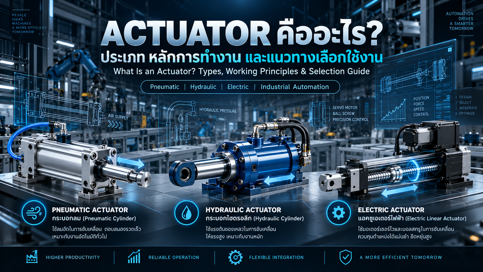
What Is an Actuator? Types, Working Principles and Selection Guide for Industrial Automation
Understanding Pneumatic, Hydraulic and Electric Actuators, Force Calculations, Stroke, Speed, Positioning Accuracy and Industrial Machinery Applications
Actuators are essential components of modern industrial machinery and automated manufacturing systems.
From pneumatic clamps and hydraulic presses to servo-driven linear motion systems, actuators convert available energy into mechanical force and movement.
They are widely used in assembly machines, conveyor systems, industrial robots, material handling equipment, inspection stations and customized automation machinery.
However, selecting an actuator requires more than matching its physical dimensions or maximum output force.
Engineers must also consider operating loads, stroke, speed, acceleration, accuracy, cycle time, environmental conditions and safety requirements.
This guide explains the main types of actuators, their working principles, practical calculations and important selection criteria.
1. What Is an Actuator?
An actuator is a device that converts energy into mechanical force or motion to operate a mechanism or control a machine.
The energy source may be:
Compressed Air
Hydraulic Pressure
Electrical Power
The mechanical output may be linear motion, rotary motion or another defined movement.
Common Applications
Pushing and transferring workpieces
Clamping components
Opening and closing machine doors
Lifting machine assemblies
Controlling linear positioning
Rotating mechanical mechanisms
Operating industrial valves
Moving products through automation systems
Actuators provide the physical motion required to execute commands from industrial control systems.
2. How Does an Actuator Work?
In a PLC-controlled automation system, the basic control sequence may be represented as:
Sensor → PLC → Output Device / Drive → Actuator → Mechanical Movement → Feedback
For example, a photoelectric sensor detects a workpiece approaching a station.
The PLC evaluates the required operating conditions and sends a signal to a solenoid valve.
The valve directs compressed air into a pneumatic cylinder, causing the piston rod to extend.
A magnetic cylinder sensor then confirms that the cylinder has reached the intended position.
After confirmation, the PLC permits the next manufacturing operation.
The control arrangement may differ for hydraulic or electric systems, but the basic purpose remains the same.
3. Main Types of Actuators
Industrial actuators are commonly classified by their energy sources.
Pneumatic Actuators
Use compressed air to generate mechanical force and movement.
Hydraulic Actuators
Use pressurized hydraulic fluid to create force and motion.
Electric Actuators
Use electrical power, motors and suitable transmission mechanisms.
Actuators may also be classified by output motion.
Linear Actuator: Produces straight-line movement.
Rotary Actuator: Produces rotational movement.
These classifications can be combined, such as a pneumatic rotary actuator or an electric linear actuator.
4. Pneumatic Actuators
Pneumatic actuators convert compressed-air energy into mechanical motion.
A pneumatic cylinder typically contains a piston inside a cylindrical chamber.
When compressed air enters the chamber, pressure acts on the piston area and produces force.
Common Types
Single-Acting Cylinder
Uses compressed air to produce motion in one direction, with a spring or external force providing the return movement.
Double-Acting Cylinder
Uses compressed air for both extension and retraction.
Compact Cylinder
Designed for installations where axial space is limited.
Guided Cylinder
Includes guiding components to accommodate specified lateral loads and moments.
Rodless Cylinder
Transfers motion without the conventional external piston rod arrangement.
Pneumatic Rotary Actuator
Produces angular movement through a pneumatic mechanism.
Advantages
Relatively simple construction
Suitable for repetitive machine operations
Fast response in many applications
Wide availability of standardized components
Convenient integration with solenoid valves and PLC systems
Limitations
Compressed-air consumption
Air leakage and maintenance requirements
Limited inherent stiffness because air is compressible
Positioning limitations in basic on/off systems
Dependence on operating pressure and valve performance
Load-retention concerns during pressure loss
5. Pneumatic Cylinder Force Calculation
For a double-acting cylinder with a single piston rod, the theoretical extension and retraction forces differ.
Extension Force
F_extend = P × πD² / 4
Where:
F_extend = Theoretical extension force (N)
P = Applied gauge pressure (MPa)
D = Piston bore diameter (mm)
Retraction Force
F_retract = P × π(D² − d²) / 4
Where:
F_retract = Theoretical retraction force (N)
d = Piston rod diameter (mm)
Using pressure in MPa and dimensions in millimetres produces force in newtons.
The actual available force can be lower because of seal friction, exhaust back pressure and other mechanical or pneumatic losses.
6. Worked Example: Pneumatic Cylinder Ø32 mm
Assume:
Cylinder Bore = 32 mm
Rod Diameter = 12 mm
Operating Pressure = 0.6 MPa
Double-Acting Cylinder
Extension Area
A_extend = π × 32² / 4
A_extend ≈ 804.25 mm²
Extension Force
F_extend = 0.6 × 804.25
F_extend ≈ 482.55 N
Retraction Area
A_retract = π(32² − 12²) / 4
A_retract ≈ 691.15 mm²
Retraction Force
F_retract = 0.6 × 691.15
F_retract ≈ 414.69 N
The theoretical extension force is greater than the retraction force because the piston rod reduces the effective area on the retraction side.
These values should be used only as preliminary calculations.
Actual sizing requires confirmation against manufacturer data.
7. Selecting Pneumatic Cylinder Bore Size
Cylinder selection should consider more than the theoretical piston force.
Important loading conditions include:
Static Clamping
Horizontal Movement
Vertical Lifting
Accelerating Loads
Side Loads
Impact Loads
High-Speed Operation
Example: Vertical Lifting
Assume:
Load Mass = 20 kg
Upward Acceleration = 1 m/s²
Cylinder Bore = 32 mm
Operating Pressure = 0.6 MPa
Lifting During the Extension Stroke
The required idealized force is:
F_required = m(g + a)
= 20 × (9.81 + 1)
F_required = 216.2 N
The theoretical extension force is approximately 482.55 N.
The load ratio is:
Load Ratio = 216.2 / 482.55
Load Ratio ≈ 0.448
The result corresponds to approximately 44.8% of the theoretical extension force.
SMC cylinder-selection guidance uses load factors and recommends lower load ratios for certain dynamic applications.
However, the final selection must account for the actual cylinder model, friction, pressure losses, speed, guidance and operating conditions.
Vertical lifting also requires a separate assessment of uncontrolled load movement during loss of pressure.
8. Hydraulic Actuators
Hydraulic actuators use pressurized fluid to produce mechanical force or motion.
Hydraulic cylinders are widely used where high forces are required.
Typical equipment includes:
Hydraulic Presses
Industrial Clamping Systems
Heavy Material Handling
Metal Forming Machines
Industrial Lifting Equipment
Heavy-Duty Machinery
Main Components
Hydraulic Cylinder
Hydraulic Pump
Power Unit
Directional Control Valve
Pressure Control Valve
Fluid Reservoir
Hoses and Fittings
Filters
Pressure and Position Sensors
Advantages
High force capability
Suitable for demanding industrial loads
Controlled movement with appropriate valves and feedback
Flexible system configurations
Limitations
Potential fluid leakage
High-pressure safety risks
Oil contamination concerns
Fluid temperature management
Maintenance requirements for hydraulic circuits
9. Hydraulic Cylinder Force Calculation
The simplified theoretical relationship is:
F = P × A
For a hydraulic cylinder with:
Bore Diameter = 40 mm
Pressure = 5 MPa
The piston area is:
A = π × 40² / 4
A ≈ 1,256.64 mm²
The theoretical extension force is:
F = 5 × 1,256.64
F ≈ 6,283 N
This corresponds to approximately 6.28 kN.
Actual system design must account for pressure limitations, rod buckling, mechanical connections, seals and additional forces.
10. Electric Actuators
Electric actuators convert electrical energy into mechanical motion.
They may include a motor and a mechanical transmission mechanism that converts rotary motion into linear movement.
Common electric actuator systems include:
Ball Screw Actuators
Lead Screw Actuators
Belt-Driven Linear Actuators
Electric Cylinders
Servo Actuators
Stepper Actuators
Electric Rotary Actuators
Advantages
Multi-position capability
Programmable motion profiles
Controlled speed and acceleration
Suitable for precision positioning
PLC and motion-controller integration
Feedback-based control in suitable systems
Limitations
Electrical drive requirements
Potentially higher initial cost
Mechanical transmission wear
Thermal and duty-cycle limitations
Side-load and moment limitations
Additional safety requirements for suspended loads
Electric actuators vary significantly in accuracy, force capacity and mechanical construction.
The correct product must be selected according to the complete application requirements.
11. Servo Actuator vs. Stepper Actuator
Servo Actuator
Servo systems generally use feedback to control motion according to the commanded position, speed or torque.
They are commonly used in:
Precision Positioning
Automated Assembly
Machine Loading
Pick and Place
Multi-Axis Motion
High-Speed Automation
Stepper Actuator
Stepper systems produce motion through controlled motor steps.
Open-loop stepper systems may lose position if the available motor torque is insufficient.
Closed-loop stepper systems use feedback to improve motion monitoring and control.
Selection Considerations
Compare:
Torque-Speed Characteristics
Acceleration
Load Inertia
Positioning Accuracy
Repeatability
Duty Cycle
Feedback Requirements
Controller Compatibility
Total Cost
Encoder resolution or commanded step size alone does not guarantee actual machine positioning accuracy.
12. Electric Actuator Force and Speed Calculations
For a screw-driven actuator, a simplified relationship between axial force and screw torque is:
F = 2πηT / l
Where:
F = Axial force (N)
η = Screw efficiency
T = Torque at the screw (N·m)
l = Screw lead (m/rev)
Example
Assume:
Screw Lead = 10 mm/rev
Screw Torque = 2 N·m
Assumed Efficiency = 0.90
Then:
F = 2 × π × 0.90 × 2 / 0.01
F ≈ 1,131 N
This is a simplified theoretical force relationship.
The actual continuous force depends on motor performance, transmission components, operating speed and thermal limits.
Speed Calculation
For a screw actuator:
v = n × l
Where:
n = Screw rotational speed
l = Screw lead
Assume:
Speed = 3,000 rpm
Lead = 10 mm/rev
Converting rotational speed:
3,000 / 60 = 50 rev/s
Therefore:
v = 50 × 10 = 500 mm/s
The calculated speed must be evaluated against the screw's rated speed, critical speed, load, motor capability and duty cycle.
13. Linear vs. Rotary Actuators
Linear Actuator
Produces straight-line movement.
Typical applications include:
Pushing
Lifting
Clamping
Sliding
Positioning
Examples include pneumatic cylinders, hydraulic cylinders and screw-driven electric actuators.
Rotary Actuator
Produces rotational movement.
Typical applications include:
Rotary Indexing
Valve Operation
Part Rotation
Machine Positioning
Angle Adjustment
For rotational acceleration, the simplified torque relationship is:
T = J × α
Where:
T = Acceleration torque
J = Rotational inertia
α = Angular acceleration
Additional torque requirements may arise from external loads, gravity, friction and transmission losses.
14. What Is Actuator Stroke?
Stroke is the rated travel distance between defined actuator positions.
For example, a pneumatic cylinder with a 100 mm stroke provides a nominal piston travel of 100 mm.
However, the movement of the attached mechanism may be different if linkage or lever mechanisms are used.
Stroke Selection Considerations
Required working travel
Machine installation space
Mounting arrangement
Mechanical clearances
End-stop positions
Workpiece geometry
Maintenance access
Adjustment requirements
Excessive stroke may create collision risks, while insufficient stroke may prevent the mechanism from reaching its required position.
15. Actuator Speed and Cycle Time
Actuator speed affects production cycle time and machine throughput.
A simplified average-speed relationship is:
Average Speed = Stroke / Movement Time
Example
Stroke = 150 mm
Movement Time = 0.5 s
Average Speed = 150 / 0.5 = 300 mm/s
This represents average travel speed, not peak speed.
Actual actuator motion depends on acceleration, deceleration and the characteristics of the drive system.
Kinetic Energy
For a moving mass:
E = ½mv²
For a 20 kg load moving at 0.3 m/s:
E = 0.5 × 20 × 0.3²
E = 0.9 J
The stopping mechanism or actuator cushioning must be capable of safely managing the relevant kinetic energy.
16. Duty Cycle and Service Life
Duty Cycle describes the proportion of time an actuator operates during a defined cycle, when the manufacturer specifies performance in this way.
A basic relationship is:
Duty Cycle (%) = Operating Time / Total Cycle Time × 100
For example:
Operating Time = 6 s
Total Cycle Time = 10 s
Duty Cycle = 60%
However, actuator manufacturers may define rated operating modes differently.
Servo motors may require RMS torque and thermal calculations.
Pneumatic and hydraulic systems require evaluation of cycling frequency, seals, pressure conditions and heat generation.
A component that can briefly produce its maximum rated force may not be capable of maintaining that output continuously.
17. How to Select an Actuator
A practical actuator selection process should consider the following requirements.
Load and Force
Determine process forces, moving mass, friction and acceleration.
Stroke
Establish the required movement and installation dimensions.
Speed
Specify movement time, cycle time and acceleration requirements.
Accuracy and Repeatability
Determine how accurately the actuator must reach and repeat its commanded positions.
Mounting Arrangement
Check mounting interfaces, side loads and moments.
Operating Environment
Evaluate temperature, moisture, dust, chemicals and other environmental factors.
Duty Cycle
Determine operating frequency and thermal requirements.
Control Compatibility
Check the required PLC outputs, drive interfaces and feedback devices.
Safety
Evaluate crushing hazards, unexpected movement, falling loads and stored energy.
Maintenance
Consider lubrication, seals, wear components and inspection access.
Total Cost
Assess purchase price, installation, energy use and expected maintenance costs.
The best actuator is the one that satisfies the complete machine requirements rather than merely having the highest nominal force.
18. Industrial Actuator Applications
Conveyor Stopper
A pneumatic actuator can be used to operate a stopper mechanism, provided its impact loads and mechanical limits are properly evaluated.
Jig & Fixture Clamping
Pneumatic or hydraulic cylinders can generate controlled clamping forces for manufacturing operations.
Precision Positioning
Servo-driven electric actuators are often suitable for multi-position motion and programmable movement.
Heavy Pressing
Hydraulic systems are common in processes requiring significant forming or pressing forces.
Pick and Place
Pneumatic actuators may be economical for simple repetitive movements.
Electric actuators may provide greater flexibility for variable positioning.
Rotary Indexing
Rotary pneumatic or electric actuators can be used according to the required angular movement, torque and accuracy.
19. PLC Integration and Motion Control
Different actuator technologies use different control interfaces.
Pneumatic Control
PLC → Solenoid Valve → Pneumatic Cylinder
Position sensors provide feedback to the PLC.
Hydraulic Control
PLC → Hydraulic Control Valve → Hydraulic Actuator
Pressure or position sensors may be used for monitoring and control.
Electric Motion Control
PLC / Motion Controller → Motor Drive → Electric Actuator
Encoders and other feedback devices may monitor the position and operating status.
A typical automation sequence includes workpiece detection, actuator movement, position confirmation, process execution and actuator return.
Safety functions must be designed separately according to the identified risks and required safety performance.
20. Actuator Safety
Actuators can create hazardous mechanical movement and significant stored energy.
Important hazards include:
Crushing and pinching
Unexpected movement
Falling loads
Hydraulic pressure hazards
Stored compressed air
Electrical faults
Mechanical overtravel
Impact and collision
Protective measures may include:
Fixed Guards
Interlocks
Safety-Related Control Functions
Mechanical Stops
Load-Holding Devices
Safe Isolation Procedures
Pressure and Position Monitoring
Suitable Emergency Stop Functions
Preventive Maintenance
Emergency stopping must be designed according to the machine risk assessment.
Simply venting pneumatic or hydraulic pressure may be unsafe when a suspended load depends on that pressure for support.
21. Relevant Engineering Standards
ISO 4414 – Pneumatic Fluid Power
Provides general rules and safety requirements for pneumatic systems and components.
ISO 4413 – Hydraulic Fluid Power
Provides general rules and safety requirements for hydraulic systems and components.
ISO 15552 – Pneumatic Cylinder Dimensions
Specifies basic, mounting and accessory dimensions for applicable pneumatic cylinders.
ISO 12100 – Machinery Risk Assessment
Provides principles for identifying hazards, evaluating risks and reducing risks in machinery design.
ISO 13849-1 – Safety-Related Control Systems
Provides design principles for safety-related parts of machine control systems.
These standards have different scopes and should be selected according to the application.
22. Common Actuator Selection Mistakes
Selecting Based Only on Theoretical Force
Actual force may be lower due to friction and system losses.
Ignoring Extension and Retraction Differences
Single-rod cylinders usually have different effective piston areas in each direction.
Selecting an Incorrect Stroke
Insufficient or excessive stroke may cause functional or safety problems.
Ignoring Side Loads
Uncontrolled side loads may damage cylinder rods, seals and mechanical guides.
Ignoring Cushioning Requirements
High-speed motion may produce excessive stopping forces.
Ignoring Duty Cycle
An electric actuator may overheat if operated beyond its rated conditions.
Ignoring Vertical Load Retention
Suspended loads require appropriate protection against unintended movement.
Overlooking Feedback
Insufficient position feedback may cause incorrect machine sequencing.
Ignoring Manufacturer Specifications
Actuators with similar nominal dimensions may have significantly different ratings.
23. Frequently Asked Questions
What Is an Actuator?
An actuator converts energy into mechanical force or movement to operate machinery or mechanisms.
What Are the Main Types of Actuators?
The main industrial categories include pneumatic, hydraulic and electric actuators.
What Is the Difference Between a Motor and an Actuator?
A motor is an energy-to-motion conversion device. An actuator is a broader term for a device that creates controlled mechanical movement or action and may contain a motor.
How Do You Calculate Pneumatic Cylinder Force?
The theoretical extension force can be calculated using pressure multiplied by the effective piston area.
Can Pneumatic Actuators Control Multiple Positions?
Yes, using suitable position-control hardware and feedback, although basic on/off pneumatic cylinders are commonly used for movements between defined end positions.
Which Actuator Is Best for Precision Positioning?
Electric servo-driven actuators are often suitable, but actual positioning performance must be verified at the machine load.
Can Actuators Be Controlled by a PLC?
Yes. PLC systems commonly control actuator valves and motor drives while monitoring relevant feedback signals.
Which Actuator Is Best for Heavy Loads?
Hydraulic actuators are commonly used for high-force applications, although final selection depends on force, speed, accuracy and safety requirements.
24. Conclusion
Actuators are fundamental components of industrial automation and modern machinery.
They convert electrical, pneumatic or hydraulic energy into the mechanical movement required for production processes.
Pneumatic actuators are widely used for repetitive movement, clamping and handling tasks.
Hydraulic actuators are suitable for many applications involving substantial forces.
Electric actuators provide programmable motion control and are frequently used for precision positioning.
However, no single actuator type is ideal for every machine.
Successful actuator selection requires consideration of force, stroke, speed, accuracy, acceleration, mechanical loads, duty cycle, control integration and safety.
A well-selected actuator is not simply the strongest or fastest option. It is the actuator that delivers the required motion reliably, efficiently and safely throughout its intended service life.
AC DESIGN AND DEVELOPMENT – Industrial Automation & Machine Design Solutions
AC DESIGN AND DEVELOPMENT CO., LTD. provides customized industrial engineering and manufacturing solutions.
Our services include:
Automation Machine Design and Manufacturing
Custom Jig & Fixture
Conveyor Systems
Machine Parts Manufacturing
Industrial Steel Structures
Custom Engineering Solutions
Our engineering approach focuses on selecting suitable mechanical components, motion systems and control solutions for practical manufacturing applications.
Industrial Engineering and Automation Solutions Across Thailand
Website: https://www.acdesignanddevelopment.com/
Tel: +66 82-210-0792
Technical Disclaimer: Calculations in this article are simplified educational examples. Actual actuator selection and machine design must be verified using manufacturer specifications, operating conditions, appropriate engineering analysis and applicable safety requirements.