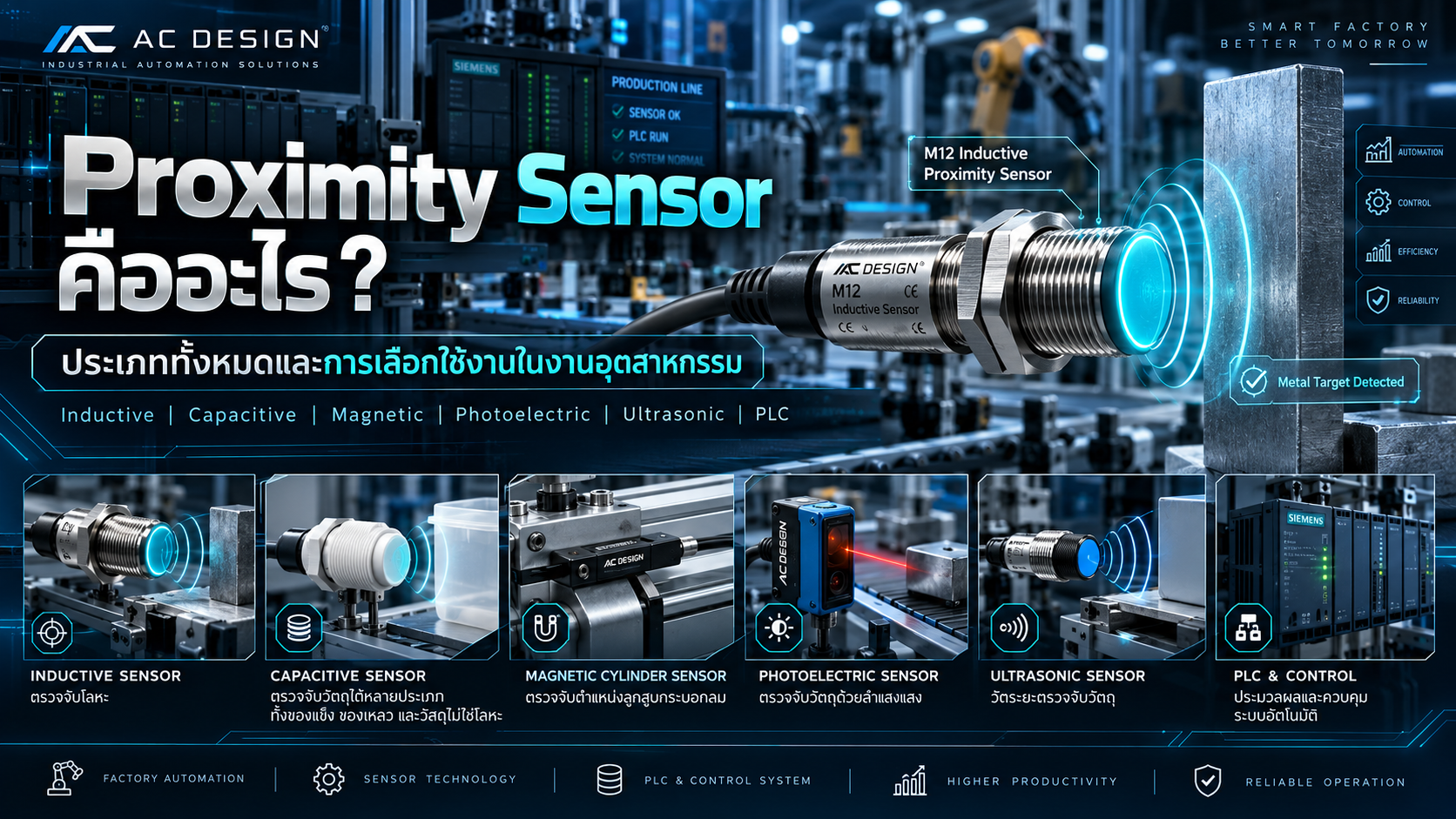
What Is a Proximity Sensor? Types, Working Principles and Industrial Selection Guide
Understanding Inductive, Capacitive, Magnetic, Photoelectric, Ultrasonic, Laser and Radar Sensors, Including PNP/NPN Wiring, Sensing Distance and PLC Integration
Proximity sensors are essential components of modern industrial automation and manufacturing machinery.
They are widely used to detect the presence, position or movement of objects without requiring direct mechanical contact.
Applications include conveyor systems, automated assembly machines, robotic handling equipment, production inspection stations, pneumatic cylinders and custom industrial machinery.
For example, a proximity sensor can detect when a metal workpiece reaches a fixture, confirm the position of a pneumatic cylinder or count products passing through a conveyor system.
However, industrial proximity sensors use different sensing technologies, each with its own advantages, limitations and installation requirements.
Selecting the wrong sensor may result in unreliable detection, false signals, missed products or incompatible PLC input wiring.
This guide explains the major proximity sensor technologies, their operating principles and practical selection criteria for industrial applications.
1. What Is a Proximity Sensor?
A proximity sensor is a device that detects the presence or proximity of a target object without direct mechanical contact.
The detection principle may involve:
Electromagnetic induction
Capacitance variation
Magnetic fields
Optical sensing
Ultrasonic waves
Radio-frequency electromagnetic waves
When a target enters the sensing region, the sensor detects a physical change and converts it into an electrical signal or digital data.
The output may be connected to:
PLC Controllers
Robot Controllers
Industrial Counters
Machine Controllers
Data Acquisition Systems
Industrial Communication Modules
Common Applications
Detecting workpiece presence
Confirming machine positions
Detecting metal components
Monitoring pneumatic cylinders
Counting manufactured products
Monitoring material levels
Measuring distances
Supporting automated inspection
Controlling manufacturing sequences
2. How Does a Proximity Sensor Work?
A proximity sensor generally operates through three functional stages.
Detection
The sensor generates or receives a physical signal associated with the target object.
Signal Processing
An internal electronic circuit evaluates the signal and determines whether the detection conditions have been satisfied.
Output
The sensor sends an ON/OFF signal, analog measurement or communication data to the connected control system.
For example, an inductive sensor installed beside a conveyor detects a metal component approaching its sensing face.
The PLC receives the detection signal and starts the next programmed operation.
3. Main Types of Proximity Sensors
The major industrial sensing technologies include:
Inductive Proximity Sensors
Capacitive Proximity Sensors
Magnetic Sensors
Photoelectric Sensors
Fiber Optic Sensors
Laser Sensors
Ultrasonic Sensors
Radar Sensors
Eddy Current Displacement Sensors
These technologies may be classified differently depending on the manufacturer and application.
For example, fiber optic sensors are commonly a form of optical sensing, while laser sensors may be used for either switching detection or continuous distance measurement.
The selection must therefore consider the actual sensing principle rather than only the product category name.
4. Inductive Proximity Sensors
An inductive proximity sensor uses electromagnetic induction to detect metallic objects.
The sensor generates an alternating electromagnetic field near its sensing face.
When a conductive metal target approaches, eddy currents are induced within the material.
These currents affect the sensor's electromagnetic behavior.
The sensor evaluates the change and switches its output when the specified conditions are reached.
Detectable Materials
Carbon Steel
Stainless Steel
Aluminum
Copper
Brass
Other suitable conductive metals
Industrial Applications
Metal workpiece detection
Gear position detection
Metal fixture monitoring
Conveyor part counting
Mechanical position confirmation
Machine stopper detection
Advantages
Contactless detection
Suitable for metallic targets
No conventional mechanical switching contact
High switching speeds in suitable models
Wide selection of industrial housings
Limitations
Not generally suitable for detecting plastic or paper directly
Sensing distance varies with target material
Nearby metal may affect installation
Target size and geometry influence detection
5. Inductive Sensor Sensing Distance
Sensing Distance describes the distance between the sensor and target under defined conditions.
Important terminology includes:
Nominal Sensing Distance (Sn)
The rated sensing distance used to identify the sensor.
Real Sensing Distance (Sr)
The actual sensing distance determined under specified reference conditions.
Usable Sensing Distance (Su)
A sensing distance range accounting for defined variations in operating conditions.
Assured Operating Distance (Sa)
The specified operating distance range within which detection is assured under the relevant conditions.
A sensor with a nominal sensing distance of 8 mm should not automatically be installed exactly 8 mm away from the target.
The actual design must consider the assured operating distance, target material, geometry, temperature and mechanical tolerances.
6. Understanding Reduction Factors
Conventional inductive sensors may have different sensing distances for different metals.
This behavior is represented by a Reduction Factor.
Representative values for selected sensor technologies may include:
| Material | Example Factor |
|---|---|
| Mild Steel | 1.0 |
| Stainless Steel | 0.85 |
| Aluminum | 0.40 |
| Brass | 0.40 |
| Copper | 0.30 |
These values are examples rather than universal specifications.
Calculation Example
Assume:
Nominal Sensing Distance = 8 mm
Aluminum Reduction Factor = 0.40
Estimated reference sensing distance:
8 × 0.40 = 3.2 mm
The result illustrates how aluminum detection distance may be significantly shorter than the rated distance for steel.
The actual assured operating distance must still be verified using the selected sensor's technical documentation.
Factor 1 Sensors
Factor 1 inductive sensors are designed to provide more consistent sensing distances across several metal types.
They can be useful when steel, stainless steel and non-ferrous metals must be detected using the same sensor arrangement.
7. Flush and Non-Flush Mounting
Inductive sensors are available with different mounting configurations.
Flush-Mountable Sensors
Designed for installation with the sensing face level with the surrounding metal surface, according to the manufacturer's requirements.
Non-Flush-Mountable Sensors
Typically require clearance around the sensing face because surrounding metal can affect the electromagnetic field.
Some non-flush models offer longer sensing distances.
Installation Considerations
Clearance from surrounding metal
Distance between adjacent sensors
Sensor mounting depth
Bracket rigidity
Workpiece movement
Environmental exposure
Incorrect mounting can cause false triggering or reduced detection performance.
8. Capacitive Proximity Sensors
Capacitive proximity sensors detect changes in electrical capacitance caused by nearby materials.
They can detect both metallic and certain non-metallic targets.
Common Detectable Materials
Plastic
Glass
Wood
Paper
Liquids
Powders
Granular Materials
Metals
Applications
Liquid level detection
Plastic component detection
Powder and granular material monitoring
Packaging detection
Selected container-level applications
Advantages
Detects a wide range of materials
Useful for non-metal targets
Available in adjustable-sensitivity models
Suitable for certain level detection tasks
Limitations
Sensitive to material characteristics
Moisture and contamination can affect detection
May require recalibration for different materials
Detection through container walls depends on material and thickness
9. Magnetic Proximity Sensors
Magnetic proximity sensors detect magnetic fields or changes associated with magnetic targets.
They are commonly used for pneumatic cylinder position detection.
Reed Switch
A reed switch uses magnetically operated contacts that change state when exposed to a suitable magnetic field.
Hall Effect Sensor
A Hall Effect Sensor uses semiconductor technology to detect magnetic fields.
Depending on its design, it may be used for position, speed or rotational sensing.
Applications
Pneumatic cylinder end-position detection
Magnetic target detection
Rotating mechanism monitoring
Selected linear position sensing
A magnetic cylinder sensor must be compatible with the specific cylinder and magnetic piston arrangement.
10. Photoelectric Sensors
Photoelectric sensors use light to detect objects.
They are widely used in conveyor systems, packaging machinery and automated production lines.
Through-Beam Sensor
Uses separate transmitter and receiver units.
An object is detected when it interrupts or changes the beam condition.
Retro-Reflective Sensor
Uses a sensor and a reflector.
The sensor monitors reflected light from the reflector and detects interruptions according to its operating principle.
Diffuse Reflective Sensor
Detects light reflected directly from the target object.
Performance can depend on object color, surface finish, shape and distance.
Background Suppression Sensor
Designed to detect targets within a selected range while reducing unwanted influence from objects farther away.
Typical Applications
Product counting
Conveyor detection
Packaging equipment
Part presence verification
Material handling
The correct optical sensing principle must be selected based on target properties and mounting conditions.
11. Fiber Optic Sensors
Industrial fiber optic sensors commonly use optical fibers to transmit and receive light from a remote sensing point.
A typical system may include:
Fiber Amplifier
Fiber Optic Cable
Fiber Sensing Head
Switching Output
Advantages
Compact sensing heads
Suitable for restricted installation spaces
Useful for detecting small components
Flexible sensing-head positioning
Electronics can be located away from the sensing point
Applications
Small electronic components
Pin detection
Precision assembly fixtures
Compact automated inspection systems
12. Laser Sensors
Laser sensors use laser light for object detection or distance measurement.
The measuring principle depends on the sensor design and may include optical triangulation or time-of-flight methods.
Applications
Small component detection
Edge detection
Height measurement
Object position verification
Distance measurement
Important Selection Parameters
Measurement range
Spot size
Resolution
Repeatability
Measurement accuracy
Response time
Surface compatibility
Laser safety classification
Laser technology does not automatically guarantee superior measurement accuracy.
The actual performance must be verified from the selected sensor's specifications.
13. Ultrasonic Sensors
Ultrasonic sensors use high-frequency sound waves to detect objects or measure distances.
Many ultrasonic distance sensors work by transmitting a sound pulse and measuring the time required for the echo to return.
A simplified distance formula is:
Distance = Speed of Sound × Echo Time / 2
Example
Assume:
Speed of Sound = 343 m/s
Round-Trip Echo Time = 0.01 s
Then:
Distance = 343 × 0.01 / 2
Distance = 1.715 m
The calculation is simplified because the speed of sound varies with environmental conditions, particularly temperature.
Applications
Liquid level measurement
Box detection
Object distance monitoring
Selected difficult optical sensing applications
Limitations
Blind zones
Temperature effects
Sound-absorbing materials
Unfavorable reflection angles
Potential interference between neighboring sensors
14. Radar and Eddy Current Sensors
Radar Sensors
Radar sensors use radio-frequency electromagnetic waves to detect targets or measure distance.
They are used in selected distance and industrial level measurement applications.
Performance depends on the target, frequency, antenna beam characteristics and installation environment.
Eddy Current Displacement Sensors
Eddy current displacement sensors measure changes in electromagnetic coupling between a probe and a conductive metal surface.
They are commonly used for:
Shaft displacement measurement
Shaft vibration monitoring
Metal gap measurement
Precision displacement monitoring
These devices are generally measurement sensors rather than simple ON/OFF proximity switches.
15. PNP vs. NPN Sensors
PNP and NPN describe common transistor output configurations used in industrial DC sensors.
PNP – Sourcing Output
When switched ON, a PNP output sources positive voltage to the connected load or PLC input.
NPN – Sinking Output
When switched ON, an NPN output sinks current toward the negative supply or 0V reference.
| Feature | PNP | NPN |
|---|---|---|
| Output Behavior | Sources positive voltage | Sinks toward 0V |
| Typical Active State | Positive output | Low-side connection |
| Typical PLC Input Common | 0V | +24V |
| Selection Requirement | Compatible input circuit | Compatible input circuit |
Common Three-Wire Color Convention
For many DC industrial sensors:
Brown = +24VDC
Blue = 0VDC
Black = Switching Output
These colors must always be verified against the actual product wiring diagram.
Important PLC Wiring Note
PLC input modules may use the terms sinking and sourcing from the perspective of the input circuitry.
Therefore, engineers should verify current flow and terminal wiring rather than selecting a sensor based only on terminology.
16. Normally Open and Normally Closed Outputs
NO – Normally Open
The switching output is inactive when the target is absent and becomes active when the target is detected, according to the normal powered operating condition.
NC – Normally Closed
The switching output is active when the target is absent and becomes inactive when the target is detected.
| Target Condition | NO | NC |
|---|---|---|
| Target Absent | OFF | ON |
| Target Detected | ON | OFF |
This describes normal switching behavior.
It does not mean an NC sensor automatically provides a safety-rated signal or remains energized during power failure.
17. Two-Wire, Three-Wire and Four-Wire Sensors
Two-Wire Sensors
Use two conductors and may operate with DC, AC or specialized interfaces.
Compatibility must be checked because some designs have off-state leakage current and on-state voltage drop.
Three-Wire Sensors
Commonly provide separate positive supply, negative supply and switching output connections.
PNP and NPN versions are widely available.
Four-Wire Sensors
May provide complementary outputs or additional functions depending on the design.
The actual pin assignment must be verified.
NAMUR Sensors
NAMUR sensors use low-level current signaling and require a compatible switching amplifier or interface.
They are used in selected industrial process and hazardous-area applications.
NAMUR sensors should not be connected directly to ordinary PLC digital inputs without verifying the required interface.
18. Switching Frequency and Response Time
Sensor response characteristics are important in high-speed machinery.
Switching Frequency
Indicates switching capability under specified conditions, commonly expressed in hertz.
Response Time
Describes how quickly the sensor responds to a change in target conditions.
Example: High-Speed Conveyor
Assume:
Conveyor Speed = 60 m/min
Object Length Along Travel = 15 mm
Convert speed:
60 m/min = 1,000 mm/s
The approximate object detection window is:
Time = 15 / 1,000
Time = 0.015 s = 15 ms
The sensor and PLC input system must reliably detect this short signal.
Important factors include:
Sensor response time
PLC input filtering
Minimum detectable pulse width
PLC scan behavior
High-speed input capability
Signal stability
A sensor with a high switching frequency does not automatically guarantee that the entire control system can capture every product.
19. Hysteresis and Repeatability
Hysteresis
Hysteresis is the difference between the sensor's switching point when a target approaches and its release point when the target moves away.
It helps prevent unstable switching near the detection threshold.
Repeatability
Repeatability describes the consistency of detection behavior under specified conditions.
These characteristics are especially important when proximity sensors are used for mechanical position confirmation.
20. Environmental Protection and IP Rating
Industrial sensors may be exposed to:
Dust
Coolant
Oil
Water
Heat
Mechanical vibration
Electrical interference
Metal chips
Humidity
IP67
Indicates a defined level of protection against dust and water under the relevant testing conditions.
IP69 / IP69K
Indicates protection against particular high-pressure, high-temperature water cleaning conditions according to the applicable standard.
An IP rating alone does not establish resistance to all industrial chemicals or cleaning agents.
Material compatibility must be verified separately.
21. How to Select a Proximity Sensor
A practical selection process should evaluate:
Target Material
Choose an appropriate detection technology for metals, plastics, liquids, packaging or magnetic targets.
Sensing Distance
Determine the actual detection gap and select a sensor with adequate operating margin.
Target Dimensions
Verify that the target is large enough for reliable detection.
Motion Speed
Check response time and control-system input requirements.
Output Configuration
Select compatible PNP, NPN, relay, analog or communication output.
Switching Function
Determine whether NO, NC or complementary output is required.
Supply Voltage
Verify electrical supply compatibility.
Installation Arrangement
Check mounting style, housing dimensions and metal clearance requirements.
Environmental Conditions
Evaluate protection rating, operating temperature, chemicals and mechanical vibration.
Maintenance
Consider accessibility, cleaning and spare-part availability.
Safety Requirements
Determine whether the sensor is used only for standard machine control or forms part of a safety-related control function.
22. Practical Industrial Selection Examples
| Application | Suitable Sensor Technology |
|---|---|
| Detecting a Steel Part on a Fixture | Inductive |
| Detecting a Cardboard Box | Photoelectric |
| Detecting a Magnetic Cylinder Piston | Magnetic |
| Monitoring Plastic Granules | Capacitive |
| Measuring Object Distance | Laser or Ultrasonic |
| Detecting Small Assembly Components | Fiber Optic or Laser |
| Detecting Multiple Metal Types | Suitable Factor 1 Inductive |
| Measuring Shaft Displacement | Eddy Current |
Final selection must consider the actual material properties, required range and operating environment.
23. Proximity Sensors and PLC Integration
Industrial proximity sensors are commonly connected to PLC digital inputs.
Typical compatible control platforms include:
Mitsubishi PLC
Siemens PLC
Omron PLC
Keyence PLC
Allen-Bradley PLC
Example Automation Sequence
The conveyor starts.
A proximity sensor detects an arriving workpiece.
The PLC commands the conveyor to stop.
A positioning actuator moves the workpiece.
A clamp secures the workpiece.
Sensors confirm the required conditions.
The production process begins.
The workpiece is released and transferred.
Before installation, engineers must verify the PLC input circuit, supply voltage, sensor output type, response time and wiring details.
For Mitsubishi FX series PLCs, the exact input wiring depends on the CPU or extension module model.
24. What Is an IO-Link Proximity Sensor?
IO-Link is a point-to-point industrial communication technology for compatible sensors and actuators.
It enables additional data exchange beyond a conventional discrete switching signal.
Depending on the device, information may include:
Sensor identification
Process values
Switching status
Diagnostic data
Parameter settings
Warning information
Benefits
Easier device configuration
Better diagnostic visibility
Additional process information
Improved maintenance support
Simplified device replacement in supported systems
IO-Link requires compatible devices and an IO-Link Master.
Standard IO-Link communication does not automatically make a sensor safety-rated.
25. Can a Proximity Sensor Be Used for Machine Safety?
A standard proximity sensor should not automatically be used as a safety device.
For example, detecting a machine guard with an ordinary inductive sensor does not necessarily satisfy machinery safety requirements.
Safety-related applications may require:
Safety Interlock Switches
Safety-Rated Non-Contact Sensors
Safety Controllers
Safety PLCs
Appropriate diagnostic arrangements
Validated safety functions
The required safety performance must be determined from a machinery risk assessment.
ISO 13849-1 provides design requirements for safety-related parts of control systems.
Simply installing two ordinary sensors does not automatically produce a safety-rated system.
26. Common Proximity Sensor Problems
The Sensor LED Turns On but the PLC Input Does Not
Possible causes include incompatible PNP/NPN wiring, incorrect PLC input common configuration or a wiring fault.
Metal Detection Range Is Too Short
The target material may have a lower reduction factor than the reference material.
The Sensor Remains Continuously Activated
Nearby metal, contamination or incorrect mounting may affect detection.
The Sensor Switches Intermittently
The target may be positioned near the sensing threshold or exposed to vibration.
High-Speed Objects Are Missed
The sensor or PLC input may not respond quickly enough.
Black or Reflective Objects Are Difficult to Detect
Optical sensor performance may vary with surface reflectivity and target geometry.
The Sensor Fails Prematurely
Environmental exposure, cable damage, mechanical impact or electrical faults may be responsible.
Two Nearby Sensors Interfere
Electromagnetic or acoustic interference may occur if spacing and installation requirements are not followed.
27. Proximity Sensor Maintenance
Recommended inspection activities include:
Inspecting cables and connectors
Cleaning sensing faces
Checking mechanical mounting
Verifying sensing distance
Testing with representative targets
Checking PLC input status
Investigating recurring faults
Recording replacement part numbers
Following manufacturer-specific maintenance instructions
Preventive maintenance helps reduce unexpected detection problems and supports reliable automated operation.
28. Relevant Engineering Standards
IEC 60947-5-2
Requirements for proximity switches within its specified scope, including inductive, capacitive, ultrasonic, photoelectric and non-mechanical magnetic sensing technologies.
IEC 60947-5-7
Requirements for applicable proximity devices with analog outputs or digital representation of sensing values.
IEC 61131-9
Defines the IO-Link / SDCI communication interface for compatible sensors and actuators.
IEC 60529
Defines degrees of protection provided by equipment enclosures using the IP Code.
ISO 13849-1
Provides design principles and requirements for safety-related parts of machinery control systems.
The relevant standards must be selected according to the sensor type and actual function.
29. Frequently Asked Questions
What Is a Proximity Sensor?
A proximity sensor detects the presence or position of a nearby object without direct mechanical contact.
What Are the Main Types?
Common types include inductive, capacitive, magnetic, photoelectric and ultrasonic sensors, along with specialized optical, laser, radar and eddy current devices.
Can an Inductive Sensor Detect Plastic?
Standard inductive sensors are designed for conductive metallic targets. Plastic detection generally requires a different technology.
What Is the Difference Between PNP and NPN?
PNP sensors source positive voltage, while NPN sensors switch toward the negative supply reference.
What Is the Difference Between NO and NC?
Normally Open outputs activate when a target is detected, while Normally Closed outputs generally deactivate when a target is detected under normal powered conditions.
Can an Inductive Sensor Detect Stainless Steel?
Many inductive sensors can detect stainless steel, but the sensing distance may differ from that for mild steel.
What Do M12 and M18 Mean?
For cylindrical threaded sensors, M12 and M18 typically describe housing thread sizes.
They do not directly specify sensing distance.
Can Proximity Sensors Work with Mitsubishi PLCs?
Yes, provided the electrical output and wiring are compatible with the selected PLC input module.
Can Proximity Sensors Detect High-Speed Objects?
Yes, if the sensor response characteristics and the PLC input system support the required detection timing.
Are Standard Proximity Sensors Safety Devices?
Not automatically. Safety-related detection requires an appropriately designed and validated system.
30. Conclusion
Proximity sensors are fundamental components of industrial automation and modern machine control.
Inductive sensors are widely used for detecting metal components.
Capacitive sensors can detect a variety of materials, including selected liquids and non-metallic objects.
Magnetic sensors are useful for detecting magnetic targets and pneumatic cylinder positions.
Photoelectric and fiber optic sensors are widely used in conveyor and assembly applications.
Laser and ultrasonic sensors provide additional detection and distance-measurement capabilities.
Radar and eddy current sensors serve more specialized measurement applications.
However, selecting the correct proximity sensor requires more than choosing the detection technology.
Engineers must also evaluate sensing distance, target material, object dimensions, motion speed, installation geometry, output type, environmental resistance and PLC compatibility.
The best proximity sensor is not necessarily the one with the longest sensing distance. It is the sensor that provides reliable detection under the actual operating conditions of the machine.
AC DESIGN AND DEVELOPMENT – Industrial Automation & Machine Design Solutions
AC DESIGN AND DEVELOPMENT CO., LTD. provides custom industrial engineering and machinery manufacturing solutions.
Our services include:
Automation Machine Design and Manufacturing
Custom Jig & Fixture
Conveyor Systems
Machine Parts Manufacturing
Industrial Steel Structures
Custom Engineering Solutions
Our engineering approach focuses on selecting suitable sensing technologies, mechanical components and control systems for reliable manufacturing applications.
Industrial Engineering and Automation Solutions Across Thailand
Website: https://www.acdesignanddevelopment.com/
Tel: +66 82-210-0792
Technical Disclaimer: This article provides general engineering information. Sensor selection, wiring and installation must be verified using the specific manufacturer's datasheet, PLC hardware documentation and applicable electrical and machinery safety requirements.