Electrical Drawing Symbols: A Complete Guide for Industrial Control Circuits
Understanding Electrical Schematic Symbols, IEC Standards, Relays, Contactors, Motors, Sensors, PLCs and Industrial Control Panel Drawings
Electrical schematic diagrams are essential documents in industrial machinery design, electrical panel manufacturing and automation system maintenance.
They represent electrical components, connections and operating relationships through graphical symbols rather than physical equipment drawings.
For electrical engineers, automation technicians and maintenance personnel, understanding these symbols is important for circuit analysis, installation verification, troubleshooting and safe machine operation.
This guide introduces common electrical drawing symbols, equipment identification methods and practical examples used in industrial machinery and control systems.
1. What Are Electrical Drawing Symbols?
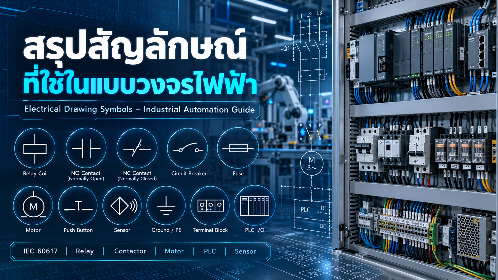
Electrical drawing symbols are graphical representations of components and electrical functions in schematic diagrams.
They help engineers communicate circuit information consistently and efficiently.
Typical schematic diagrams represent:
Power supplies and conductors
Circuit breakers and fuses
Switches and push buttons
Relays and contactors
Motors and drives
Sensors and measuring devices
PLC input/output circuits
Grounding and terminal connections
Understanding a schematic requires more than recognizing individual symbols. Readers must also interpret component reference designations, terminal numbers, wire identifiers and connections between circuit sections.
2. Important Electrical Drawing Standards
IEC 60617 – Graphical Symbols for Diagrams
IEC 60617 provides standardized graphical symbols for electrical and electrotechnical diagrams.
The IEC 60617 database contains more than 1,500 symbols covering conductors, switching devices, protective equipment, electronic components and other applications.
IEC 61082-1 – Preparation of Electrotechnical Documents
IEC 61082-1 establishes rules for presenting electrical engineering documents, including circuit diagrams, connection documents and technical drawings.
IEC 81346-2 – Reference Designations
IEC 81346-2 establishes classification principles and associated letter codes for technical objects and reference designations.
IEC 60204-1 – Electrical Equipment of Machines
IEC 60204-1 addresses general safety requirements for the electrical equipment of industrial machinery.
IEC 61131-3 – PLC Programming Languages
IEC 61131-3 covers programmable controller languages, including Ladder Diagram (LD), Function Block Diagram (FBD) and Structured Text (ST).
Important: IEC and ANSI/NEMA drawing conventions may differ. Actual project documentation should always be interpreted using its drawing legend, applicable standards and manufacturer specifications.
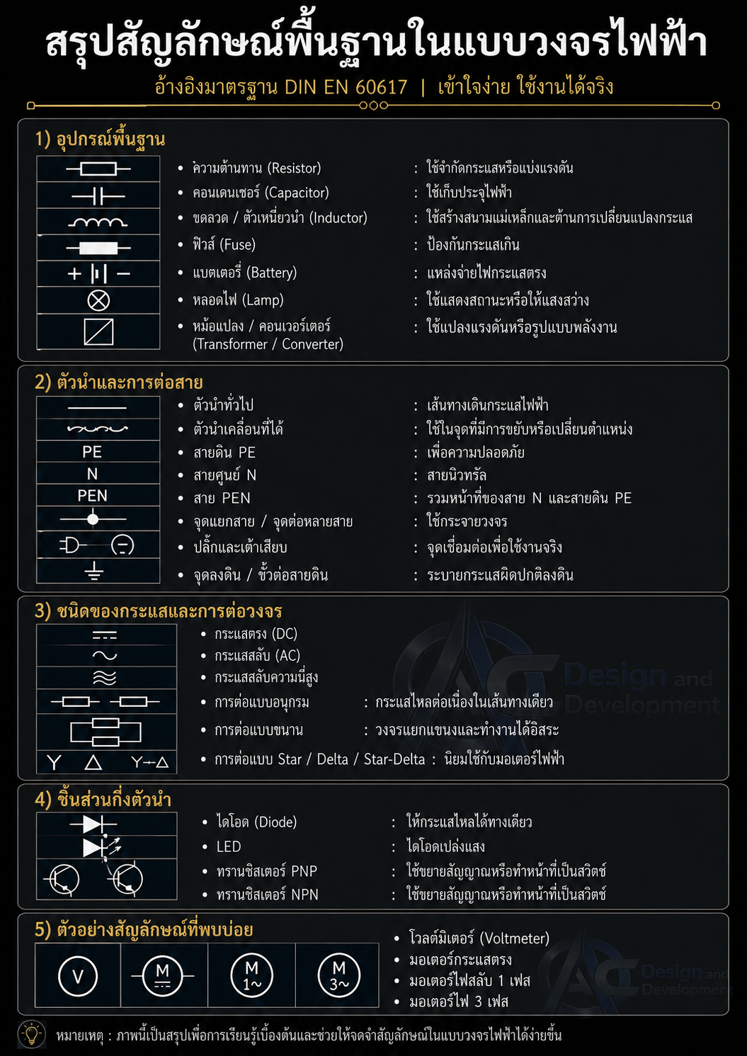
3. Basic Electrical Symbols and Identifiers
| Symbol or Identifier | Description | Application |
|---|---|---|
| Conductor | Electrical connection line | Circuit wiring |
| Junction | Connected conductor intersection | Wire connections |
| AC / ~ | Alternating current | AC supply |
| DC / ⎓ | Direct current | DC supply |
| L1, L2, L3 | Line conductors | Three-phase systems |
| N | Neutral conductor | Neutral connection |
| PE | Protective Earth | Protective grounding |
| +24V | Positive DC supply | Control power |
| 0V | DC reference conductor | Control circuit return |
| Terminal | Electrical connection point | Wiring termination |
A 0VDC circuit reference must not automatically be treated as Protective Earth. Electrical bonding arrangements depend on the system design.
4. Electrical Protection Devices
Protection devices reduce risks associated with electrical faults and abnormal current conditions.
Common devices include:
| Device | Function |
|---|---|
| Circuit Breaker | Interrupts electrical circuits under specified conditions |
| MCB | Miniature Circuit Breaker |
| MCCB | Molded Case Circuit Breaker |
| Fuse | Opens a circuit under specified overcurrent conditions |
| RCD / RCCB | Residual-current protection device |
| MPCB | Motor Protection Circuit Breaker |
| Overload Relay | Motor overload protection |
| SPD | Surge Protective Device |
Equipment tags such as QF1, F1 or OL1 may appear in industrial drawings, but tag conventions vary between projects.
5. Normally Open and Normally Closed Contacts
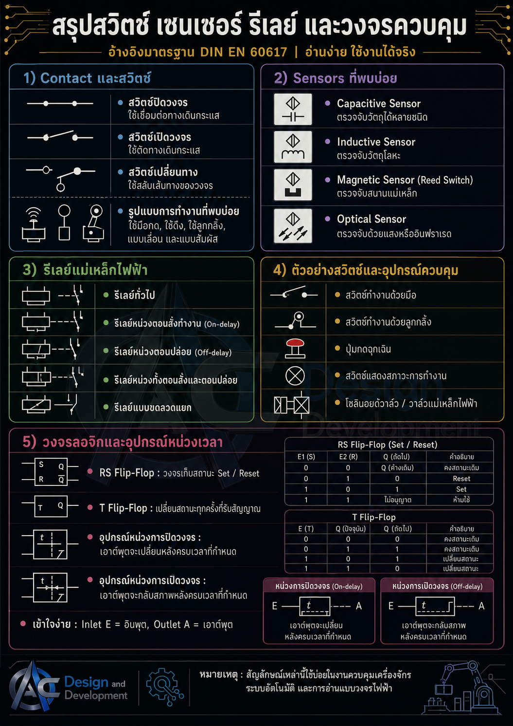
Contacts are among the most frequently used symbols in industrial control circuits.
Normally Open (NO)
An NO contact is open in its normal reference state and closes when actuated.
Typical applications include Start push buttons, relay contacts and contactor auxiliary contacts.
Normally Closed (NC)
An NC contact is closed in its normal reference state and opens when actuated.
Typical applications include Stop push buttons, monitoring contacts and conventional interlocking circuits.
Simplified Ladder Notation
Normally Open:
──| |──
Normally Closed:
──|/|──
Output Coil:
──( )──
These illustrations represent common ladder-style concepts and are not complete official IEC 60617 graphical reproductions.
For conventional electromechanical relays, the normal contact condition usually refers to the coil de-energized state.
6. Relay and Contactor Symbols
Relays and contactors are electrically operated switching devices widely used in control panels.
A relay typically includes a coil and one or more switching contacts.
A contactor commonly includes power contacts and auxiliary contacts for controlling electrical loads such as motors.
Common Terminal Markings
| Terminal | Description |
|---|---|
| A1 / A2 | Coil terminals |
| 13 / 14 | Normally Open auxiliary contact |
| 21 / 22 | Normally Closed auxiliary contact |
| 11 / 12 / 14 | Changeover COM / NC / NO on devices using this convention |
| 1/L1, 3/L2, 5/L3 | Contactor line terminals |
| 2/T1, 4/T2, 6/T3 | Contactor load terminals |
| 95 / 96 | Overload relay NC trip contact |
| 97 / 98 | Overload relay NO trip indication contact |
Actual terminal markings must be verified using the device documentation.
7. Motor and Drive Symbols
Industrial motor systems commonly include:
AC Motors
Three-Phase Motors
DC Motors
Servo Motors
Stepper Motors
Variable Frequency Drives (VFDs)
Servo Drives
Motor Brakes
Rotary Encoders
Motor symbols frequently use circular graphical elements with additional markings indicating the motor type.
Electrical diagrams may identify three-phase supply conductors as L1, L2 and L3, while motor terminals are commonly identified as U, V and W.
8. Sensor and Limit Switch Symbols
Sensors provide information about machine operating conditions.
Common devices include:
| Sensor | Function |
|---|---|
| Limit Switch | Mechanical position detection |
| Inductive Proximity Sensor | Metallic object detection |
| Capacitive Sensor | Detection based on capacitance changes |
| Photoelectric Sensor | Optical object detection |
| Pressure Switch | Pressure condition detection |
| Temperature Sensor | Temperature measurement |
| Encoder | Position or speed feedback |
| Reed Switch | Magnetic field detection |
Electronic sensors may be represented by function blocks or equipment outlines with power and signal terminals.
Sensor wiring varies depending on the output configuration, such as PNP, NPN, analog or two-wire operation.
Always use the manufacturer's wiring diagram when connecting sensors to controllers.
9. PLC Symbols and Input/Output Identification
A Programmable Logic Controller processes input signals and operates outputs according to its control program.
In electrical wiring diagrams, PLC modules are commonly shown as blocks containing terminal and channel information.
Common abbreviations include:
| Identifier | Meaning |
|---|---|
| DI | Digital Input |
| DO | Digital Output |
| AI | Analog Input |
| AO | Analog Output |
| COM | Common Terminal |
| +24V / 0V | DC supply references |
| Ethernet | Network connection |
| RS-485 | Serial communication interface |
Input and output addresses depend on the PLC manufacturer and system configuration.
For example, some Mitsubishi PLC families use X and Y addresses, while some Siemens controllers use I and Q address formats.
Electrical Wiring vs. PLC Ladder Logic
Electrical wiring diagrams show physical connections between devices.
PLC Ladder Diagrams represent programmed control logic.
A normally closed instruction in PLC logic evaluates the state of a software variable; it does not necessarily mean the physical field device uses an NC contact.
10. Terminal Blocks and Wiring Identification
Terminal blocks are used to connect internal control panel wiring to field devices and external cables.
Common information includes terminal block identifiers, terminal numbers, wire numbers, cable references and protective conductor markings.
For example, X1:05 may identify terminal number 5 on terminal block X1 under a project's naming convention.
These identifiers support wiring verification, maintenance and fault tracing.
11. Types of Electrical Engineering Drawings
Single-Line Diagram
Provides an overview of electrical power distribution.
Power Circuit Diagram
Shows the electrical connections for power loads such as motors and heaters.
Control Circuit Diagram
Represents switching logic involving relays, contactors, push buttons and control devices.
Wiring Diagram
Shows physical electrical connections and terminal references.
Terminal Diagram
Provides detailed terminal block connections.
PLC I/O Diagram
Identifies field devices connected to programmable controller input and output channels.
A complete industrial machine documentation package may contain several of these drawing types.
12. Example: Reading a Motor Start/Stop Circuit
Consider a conventional Direct-On-Line motor starter using a contactor and overload relay.
The main components include:
Circuit Breaker
Magnetic Contactor KM1
Motor Overload Relay
Start Push Button (NO)
Stop Push Button (NC)
KM1 Auxiliary NO Contact
Three-Phase Motor
Operating Sequence
Step 1: The Stop and overload contacts remain closed under normal operating conditions.
Step 2: The operator presses Start, completing the control circuit and energizing the KM1 contactor coil.
Step 3: The contactor closes its main contacts and supplies electrical power to the motor.
Step 4: A KM1 auxiliary NO contact closes, maintaining the control circuit after the Start button is released.
Step 5: Pressing Stop opens the control circuit and de-energizes the contactor.
Step 6: If the overload relay trips, its NC trip contact opens, interrupting the control circuit.
This is a conceptual example. Actual motor control wiring must be designed with suitable protective devices, safety requirements and component ratings.
13. Practical Tips for Reading Electrical Schematics
Review the Drawing Index to understand the document structure.
Read the Symbol Legend and project drawing conventions.
Identify all power supplies and voltage levels.
Separate power circuits from control circuits.
Trace equipment identifiers between drawing pages.
Follow wire numbers and terminal references.
Check contact and coil cross-references.
Verify device functions using manufacturer datasheets.
Confirm PLC I/O addresses before troubleshooting.
Review safety-related circuits separately from standard operational control.
14. Common Electrical Drawing Mistakes
Confusing NO and NC Contacts
Incorrect contact interpretation can result in an incorrect understanding of a machine sequence.
Misidentifying Relay Coils and Contacts
A relay coil and its associated contacts may appear on separate drawing pages.
Treating 0V as Protective Earth
These identifiers have different functions and must not be assumed interchangeable.
Ignoring Equipment Tags
Similar symbols may represent different devices. Reference designations are necessary for accurate identification.
Misreading Wire Intersections
Crossing lines do not always represent electrical connections.
Treating Ladder Logic as Physical Wiring
Software logic and actual electrical connections must be interpreted separately.
15. Electrical Safety Considerations
Electrical drawings are essential for understanding industrial machinery, but they must not be used as the sole basis for performing hazardous electrical work.
Before inspection, maintenance or modification, authorized personnel should isolate electrical energy sources, apply appropriate lockout/tagout procedures and verify the absence of hazardous voltage.
Safety-related functions such as Emergency Stop, safety guards and light curtains require appropriate engineering design and risk assessment.
Ordinary control relays must not be assumed to provide an adequate safety function without proper verification.
16. Frequently Asked Questions
What Is the Main IEC Standard for Electrical Drawing Symbols?
IEC 60617 is a principal international reference for standardized graphical symbols used in electrotechnical diagrams.
What Does KM Mean in an Electrical Drawing?
KM is frequently used as a contactor identifier in certain drawing conventions. Actual equipment identification must be confirmed using the project's drawing legend.
What Do A1 and A2 Mean?
A1 and A2 commonly identify relay or contactor coil terminals.
What Is the Difference Between NO and NC?
NO refers to a normally open contact, while NC refers to a normally closed contact.
Why Are Contactor Coils and Contacts Shown Separately?
Schematic diagrams often arrange components according to circuit function rather than physical device location. Reference designations and cross-references link the related components.
17. Conclusion
Understanding electrical drawing symbols is a fundamental engineering skill for industrial electrical and automation systems.
Circuit breakers, relays, contactors, motors, sensors and PLCs are represented through standardized graphical elements and project-specific reference designations.
Accurate interpretation requires understanding device functions, contact states, terminal markings, wiring references and the relationship between multiple diagrams.
Developing these skills helps engineering and maintenance teams troubleshoot efficiently, understand machine operation and support reliable industrial control system design.
Electrical schematic literacy is a foundation of safe and effective industrial automation engineering.
AC DESIGN AND DEVELOPMENT – Engineering & Automation Solutions
AC DESIGN AND DEVELOPMENT CO., LTD. provides customized engineering and industrial manufacturing solutions, including:
Automation Machine Design and Manufacturing
Jig & Fixture Systems
Conveyor Systems
Custom Machine Parts
Industrial Steel Structures
Custom Engineering Solutions
We focus on developing practical engineering solutions that support manufacturing efficiency, reliability and production quality.
Engineering and Automation Solutions Across Thailand
Website: https://acdesignanddevelopment.com/
Tel: +66 82-210-0792
Technical Disclaimer: This article is intended for educational purposes. Official standards, manufacturer documentation and applicable electrical safety requirements must be consulted for actual circuit design, installation and maintenance.