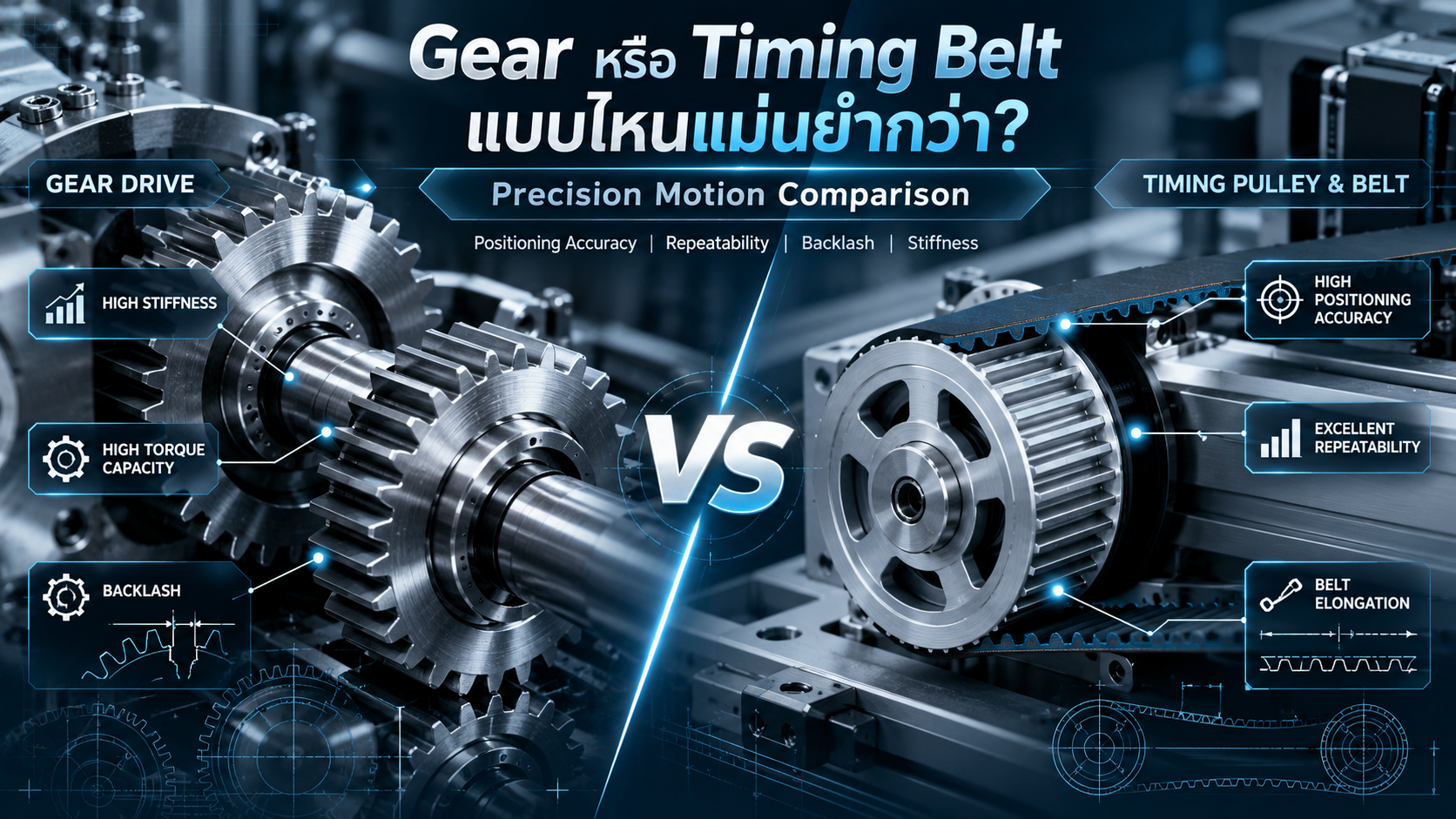
Gear vs. Timing Belt: Which Is Better for Precision Machinery and Industrial Automation?
An Engineering Comparison of Positioning Accuracy, Repeatability, Backlash, Transmission Error, Stiffness and Motion Control Performance
Precision motion control is an essential requirement in modern industrial machinery and automated manufacturing systems.
Machines used for positioning, indexing, assembly, inspection and material handling often require accurate and repeatable movement under various operating conditions.
One important mechanical design decision is selecting the appropriate power transmission system.
Two common solutions are Gear Drives and Timing Pulley & Timing Belt Systems.
Both technologies can transfer rotational motion and operate with servo motors. However, their characteristics differ in terms of mechanical stiffness, backlash, deformation, transmission distance, maintenance and positioning performance.
Selecting the correct solution requires understanding not only the nominal movement ratio but also the errors that occur between the motor and the actual machine load.
This article explains the engineering principles and practical considerations for choosing between gear drives and timing belt drives in precision machinery.
1. What Is a Gear Drive?
A gear drive is a mechanical power transmission system that uses meshing gear teeth to transfer rotation and torque between shafts.
Gears can be designed to change rotational speed, torque and shaft direction.
Common types include:
Spur Gears: Used for power transmission between parallel shafts.
Helical Gears: Provide gradual tooth engagement and are commonly used in industrial transmission systems.
Bevel Gears: Transfer rotational power between intersecting shafts.
Worm Gears: Provide high reduction ratios in certain compact arrangements.
Planetary Gear Systems: Offer compact configurations with a wide range of available reduction ratios.
Precision Gear Reducers: Designed for applications with specified backlash, torsional stiffness and transmission performance.
Advantages of Gear Drives
High torque capacity in appropriately designed systems
Potentially high torsional stiffness
Compact mechanical arrangements
Flexible speed reduction ratios
Availability of precision-grade components
Suitable for many rotary indexing applications
However, conventional gears are not automatically backlash-free or free from transmission errors.
Actual gear performance depends on manufacturing accuracy, tooth geometry, mounting conditions and mechanical loading.
2. What Is a Timing Belt Drive?
A timing belt drive uses a toothed belt that meshes with corresponding teeth on timing pulleys.
Unlike friction-based V-belt systems, synchronous belts maintain a defined rotational relationship through positive tooth engagement under appropriate operating conditions.
The main components include:
Timing Belt
Drive Pulley
Driven Pulley
Tensioning Mechanism
Shafts and Bearings
Motor or Servo Motor
Advantages of Timing Belt Drives
Suitable for longer distances between shafts
Relatively lightweight transmission arrangements
No conventional tooth lubrication requirement
Low-noise operation in many applications
Useful for linear positioning systems
Suitable for high-speed motion within rated limits
Compatible with servo-driven automation
However, timing belts have elastic properties that can influence positioning accuracy.
Belt elongation, tooth deflection and tooth clearance must be considered when evaluating precision motion.
3. Understanding Precision in Machine Design
Precision machinery requires more than high encoder resolution.
Several performance terms must be distinguished.
Resolution
Resolution describes the smallest command or measurement increment that can be distinguished by the relevant motion control system.
High resolution does not automatically guarantee high positioning accuracy.
Positioning Accuracy
Positioning accuracy describes how closely the actual machine position matches the commanded position under specified conditions.
Repeatability
Repeatability describes the consistency of repeated positioning movements under defined operating conditions.
Backlash
Backlash is lost motion caused by mechanical clearance when the transmission direction changes.
Transmission Error
Transmission error describes the difference between the actual output position and the theoretically expected position based on the nominal transmission ratio.
These characteristics must be evaluated separately when specifying machine performance.
4. Backlash in Gear and Timing Belt Systems
Gear Backlash
Conventional gears require an appropriate clearance between mating teeth.
This clearance accommodates manufacturing variation, lubrication and operating conditions.
However, backlash may produce lost motion when the direction of rotation changes.
Possible methods for reducing backlash include:
Precision gear manufacturing
Anti-backlash gear arrangements
Preloaded gear systems
Precision gear reducers
Controlled gear center distances
Accurate shaft and bearing installation
Even gear systems marketed as near-zero-backlash can experience elastic deformation and transmission error under load.
Timing Belt Backlash
Timing belt backlash may result from clearance between belt teeth and pulley grooves.
The amount depends on the tooth profile, manufacturing tolerances, operating conditions and installation tension.
Certain tooth profiles are developed for better registration performance, while others prioritize high torque transmission.
A timing belt should therefore not automatically be treated as a zero-backlash transmission.
Which System Has Less Backlash?
There is no universal answer.
A precision preloaded gear system may have lower lost motion than a conventional timing belt system.
Conversely, a precision synchronous belt arrangement may outperform ordinary gears that have relatively large tooth clearance.
The correct comparison must be based on the specifications of the selected components or measured system performance.
5. Mechanical Stiffness and Positioning Accuracy
Mechanical stiffness describes resistance to elastic deformation under applied loads.
This is particularly important for systems requiring accurate positioning while resisting external forces.
Gear Stiffness
Metal gear systems can provide high torsional stiffness, especially when combined with short, rigid shafts and suitable bearings.
Nevertheless, the complete drivetrain includes several elastic elements.
These may include:
Gear teeth
Shafts
Bearings
Gear housings
Couplings
Supporting structures
Timing Belt Stiffness
Timing belts contain flexible materials and tensile cords.
Their stiffness depends on belt construction, length, width, installation tension and operating load.
Long belt spans may produce greater elastic movement than shorter, stiffer arrangements.
Simplified Stiffness Calculation
For a system approximated by a linear spring:
Δx = ΔF / k
Where:
Δx = Elastic displacement (mm)
ΔF = Change in applied force (N)
k = Effective stiffness (N/mm)
For example, assuming an effective stiffness of 100 N/mm and a force change of 20 N:
Δx = 20 / 100 = 0.20 mm
This is a hypothetical illustration, not a standard timing belt stiffness value.
Actual calculations require manufacturer data and an appropriate mechanical model.
6. Belt Elongation and Tooth Deflection
The positioning performance of synchronous belt drives can be affected by three major mechanisms:
Belt Elongation
A belt stretches under tensile loading.
The magnitude depends on its tensile cord properties, construction, tension and operating conditions.
Backlash
Clearance between the belt teeth and pulley grooves can introduce lost motion during changes in load direction.
Tooth Deflection
Individual belt teeth deform when transmitting torque.
Tooth deflection depends on the tooth profile, number of engaged teeth, pulley size, applied torque and belt tension.
Static vs. Dynamic Registration
Static registration concerns the ability to reach a target position after a movement is completed.
Dynamic registration concerns maintaining the intended positional relationship while moving under changing loads.
Backlash is often a key concern for static positioning, while belt elongation and tooth deflection also become important for dynamic registration.
Load changes after stopping can also affect position due to elastic compliance.
7. Timing Belt Positioning Calculation
Consider a servo-driven timing belt system with:
Belt Pitch = 5 mm
Pulley Tooth Count = 20
Direct 1:1 motor-to-pulley connection
Ideal tooth engagement
No elastic deformation in the geometric model
Travel per Revolution
The linear travel per pulley revolution is:
Travel = Pitch × Tooth Count
= 5 × 20
Travel = 100 mm/rev
Travel per Degree
100 / 360 = 0.27778 mm/degree
Example of Angular Position Error
Suppose the pulley angular position differs from its target by 0.1°.
The corresponding theoretical linear position difference is:
Δx = 100 × (0.1 / 360)
Δx ≈ 0.0278 mm
This calculation establishes the geometrical relationship between pulley rotation and belt displacement.
It does not include the effects of belt deformation, backlash, pulley runout, sensor error or structural compliance.
Therefore, the result is not the complete positioning accuracy of the machine.
8. Gear Backlash Calculation
Gear backlash can also be expressed as angular lost motion.
For a simplified relationship between tangential backlash and pitch radius:
θ = j / r
Alternatively:
θ = 2j / d
Where:
θ = Angular backlash (radians)
j = Tangential backlash (mm)
d = Pitch diameter (mm)
Example
Assume:
Gear Pitch Diameter = 50 mm
Tangential Backlash = 0.05 mm
Then:
θ = 2 × 0.05 / 50
θ = 0.002 rad
Converting to degrees:
θ ≈ 0.1146°
This illustrates how a relatively small tangential clearance can correspond to measurable angular lost motion.
The actual positioning effect depends on loading direction, gear arrangement and drivetrain configuration.
9. Effect of Gear Ratio on Motion Resolution
Both gear and timing belt drives can provide speed reduction.
For a simple two-shaft transmission:
Output Speed / Input Speed = Driver Teeth / Driven Teeth
For example:
Driver = 20 Teeth
Driven = 60 Teeth
The driven shaft rotates once for every three revolutions of the driver.
A reduction ratio can improve theoretical output angular resolution relative to motor rotation.
However, this does not automatically improve overall positioning accuracy.
Backlash, transmission error, compliance and other drivetrain characteristics remain relevant.
10. Servo Motor with Gear Reducer vs. Timing Belt
Servo Motor with Gear Reducer
Common applications include:
Rotary Indexing
Compact High-Torque Drives
Rotary Positioning Axes
Precision Rotary Mechanisms
Automated Assembly Equipment
A properly selected gear reducer can provide a useful combination of torque multiplication, compactness and stiffness.
Servo Motor with Timing Belt
Common applications include:
Linear Motion Systems
Gantry Mechanisms
Pick and Place Equipment
Conveyor Synchronization
Long-Distance Mechanical Transmission
Timing belts can also help keep motor mass off moving machine assemblies.
Does Motor Encoder Resolution Guarantee Load Accuracy?
No.
An encoder mounted on the motor measures motor position.
If backlash or elastic deformation occurs between the motor and load, the actual load position may differ from the inferred position.
For demanding applications, additional feedback may be required.
Examples include:
Output Shaft Encoders
Linear Encoders
Direct Load Position Sensors
Calibration Systems
Closed-Loop Load Position Control
11. Practical Industrial Applications
Rotary Indexing Table
Precision gear reducers are often suitable when the design requires high torsional stiffness and compact torque transmission.
Linear Pick and Place
Timing belt drives can provide efficient linear motion over comparatively long travel distances.
Precision Clamping
Depending on the load and travel requirements, a rigid gear mechanism or an alternative such as a ball screw may be appropriate.
Conveyor Synchronization
Synchronous timing belts are useful for maintaining rotational relationships between shafts.
However, dynamic registration error must be assessed when accurate synchronization under changing loads is required.
Precision Rotary Axis
High-accuracy rotary applications may benefit from precision gear reducers, preloaded transmission systems or direct-drive motors.
The final choice depends on the specified accuracy, stiffness, load and control requirements.
12. Selecting the Right Timing Belt Profile
Timing belts are available in different profiles and constructions.
Common examples include:
T Profile: A trapezoidal tooth configuration used in selected power transmission and positioning applications.
AT Profile: A modified profile used in specific synchronous belt applications.
HTD Profile: Developed with an emphasis on torque-carrying capability.
GT / GT2 / GT3 Profiles: Developed to provide specific tooth-engagement and power-transmission characteristics.
Different product families and generations have different performance ratings.
Selection should consider:
Tooth geometry
Belt pitch
Pulley tooth count
Belt width
Tensile cord material
Rated load
Backlash performance
Belt stiffness
Installation tension
Operating speed and duty cycle
The smallest available pitch does not necessarily provide the best overall system accuracy.
13. Improving Gear Drive Precision
Important design considerations include:
Appropriate gear quality classification
Controlled manufacturing tolerances
Suitable backlash or preloading arrangements
Accurate gear center distances
Low runout
Rigid shafts and supporting structures
Appropriate bearings
Correct lubrication
Output position verification when necessary
ISO 1328-1 provides a tolerance classification system for the tooth flanks of applicable cylindrical involute gears.
However, individual gear accuracy does not directly guarantee the performance of a fully assembled gear transmission.
14. Improving Timing Belt Drive Precision
Important engineering practices include:
Selecting a suitable synchronous belt profile
Avoiding unnecessarily long free belt spans
Choosing appropriate belt width and tensile cord construction
Maintaining manufacturer-specified installation tension
Using precision-machined pulleys
Controlling pulley runout and alignment
Designing rigid motor and pulley mounts
Preventing tooth jumping under operating loads
Evaluating load-side position feedback
Testing dynamic and static positioning performance
The complete mechanical system should be evaluated under representative operating loads.
15. How to Choose Between Gear and Timing Belt
A practical selection process should begin with a clear motion specification.
Important parameters include:
Required positioning accuracy
Required repeatability
Allowable backlash or lost motion
Operating torque and forces
Travel distance
Rotational or linear speed
Acceleration and deceleration
Motion reversal frequency
Required mechanical stiffness
Available installation space
Environmental conditions
Maintenance requirements
Total system cost
Inspection and acceptance procedures
For high-accuracy equipment, the required values should be specified at the load or working point rather than only at the motor shaft.
The selected solution must then be verified using suitable calculations and measurement methods.
16. Other Precision Motion Technologies
Gear and timing belt systems are not the only options.
Ball Screw
Useful for many precision linear motion applications requiring controlled displacement and high mechanical stiffness.
Preloaded designs can reduce backlash.
Linear Motor
Provides direct linear force without an intermediate rotary-to-linear transmission mechanism.
Direct-Drive Rotary Motor
Eliminates the need for a mechanical reduction drive in suitable rotary applications.
Precision Gear Reducer
Provides a compact means of producing controlled rotary motion with increased output torque.
Each solution has its own cost, stiffness, accuracy, maintenance and control requirements.
17. Frequently Asked Questions
Are Gears More Accurate Than Timing Belts?
Not necessarily. Accuracy depends on the complete system, including manufacturing tolerances, backlash, stiffness, loading and feedback.
Are Timing Belts Backlash-Free?
Not all timing belt drives are backlash-free. Tooth clearance and deformation may affect positioning performance.
Can Timing Belts Be Used with Servo Motors?
Yes. Timing belts are widely used with servo motors in industrial automation and linear positioning systems.
Does a Zero-Backlash Gear Guarantee Perfect Accuracy?
No. Elastic deformation, manufacturing variation and transmission errors can remain.
Can a Timing Belt System Achieve 0.01 mm Positioning Accuracy?
It may be achievable in a properly engineered and verified system, but the result cannot be guaranteed from belt pitch or encoder resolution alone.
What Is Better for High-Torque Rotary Positioning?
A precision gear reducer may be suitable, especially when compactness and high torsional stiffness are important. The complete load and accuracy requirements must be evaluated.
What Is Better for Long-Travel Linear Motion?
Timing belt drives are often practical for long-travel motion, although demanding accuracy or stiffness requirements may favor other technologies.
18. Conclusion
Both Gear Drives and Timing Pulley & Timing Belt Systems can provide reliable motion transmission for precision industrial machinery.
Gear drives are often suitable for compact rotary mechanisms requiring high torque and torsional stiffness.
Timing belt systems are often suitable for long-distance transmission, high-speed linear motion and applications requiring flexible mechanical layouts.
Neither system is automatically superior in all precision applications.
Positioning performance depends on backlash, transmission error, mechanical stiffness, elastic deformation, load conditions and feedback system design.
Engineers should evaluate the required accuracy at the actual working point and verify system performance under representative conditions.
Precision is not determined by the transmission type alone. It is achieved through the correct integration of mechanical design, motion control, position measurement and system verification.
AC DESIGN AND DEVELOPMENT – Precision Machine Design & Automation Solutions
AC DESIGN AND DEVELOPMENT CO., LTD. provides custom industrial engineering and manufacturing solutions.
Our services include:
Automation Machine Design and Manufacturing
Custom Jig & Fixture
Conveyor Systems
Precision Mechanical Design
Custom Machine Parts
Industrial Steel Structures
Custom Engineering Solutions
We focus on practical engineering solutions that balance precision, mechanical performance, reliability and manufacturing cost.
Engineering and Industrial Automation Solutions Across Thailand
Website: https://acdesignanddevelopment.com/
Tel: +66 82-210-0792
Technical Disclaimer: The calculations and comparisons in this article are intended for engineering education. Actual system accuracy, torque capacity and reliability must be verified using manufacturer specifications, appropriate engineering analysis and measured machine performance.