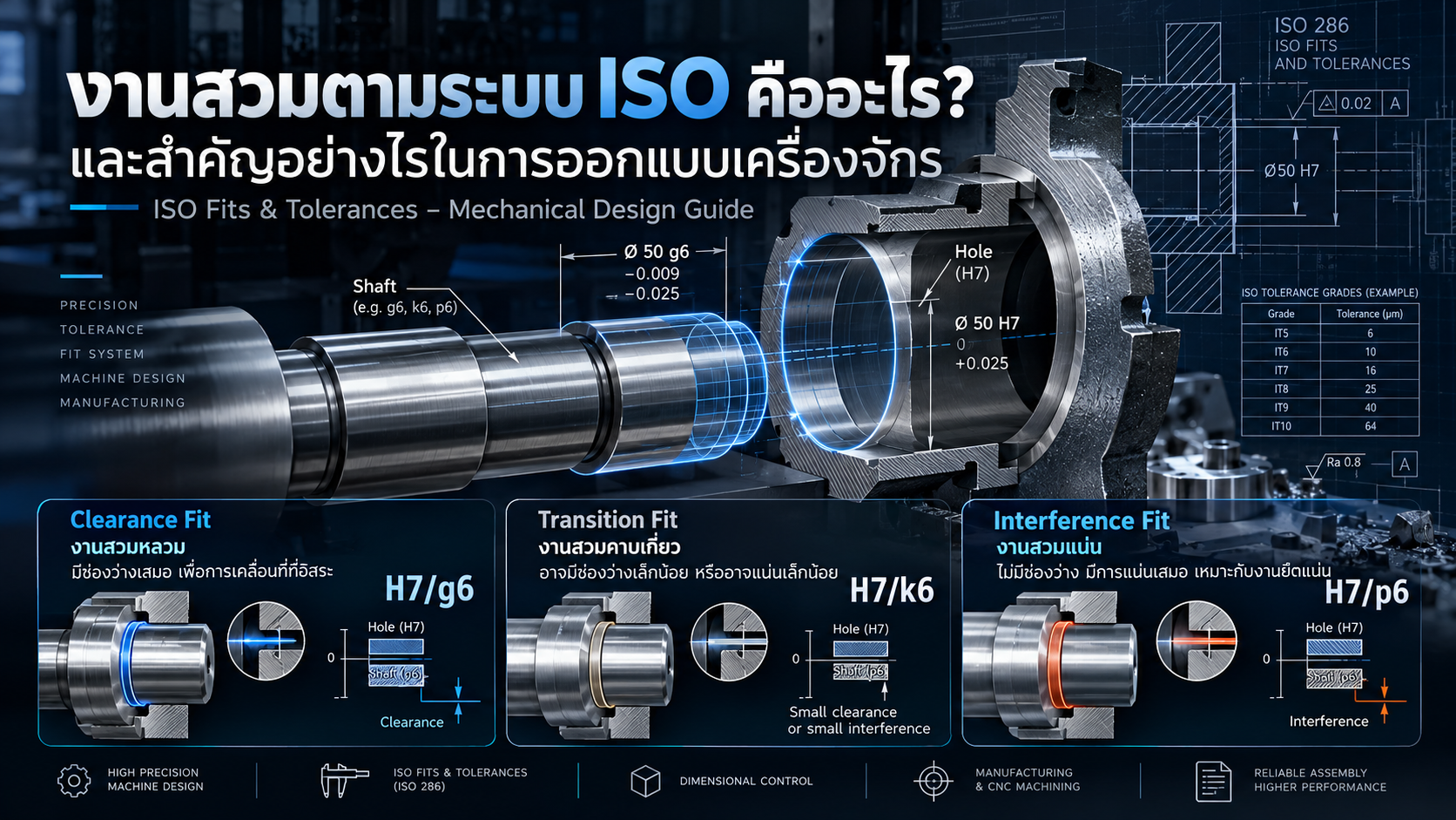
What Are ISO Fits and Tolerances? Types, Calculations and Applications in Machine Design
Understanding ISO 286, Clearance Fits, Transition Fits, Interference Fits, Hole Basis and Shaft Basis Systems for Precision Engineering
Dimensional accuracy is essential in mechanical design, precision machining and industrial machinery manufacturing.
Components such as shafts, bushings, bearings, gears and locating pins must be manufactured to suitable dimensional limits to ensure proper assembly and reliable performance.
Two components with the same nominal diameter do not necessarily fit together correctly because manufacturing processes introduce dimensional variation.
The ISO System of Limits and Fits provides a standardized method for defining acceptable size variations and the relationship between mating components.
This guide explains ISO 286 fit classifications, tolerance designations, practical calculations and their importance in machine design.
1. What Are ISO Fits and Tolerances?
An engineering fit describes the dimensional relationship between two mating features, commonly a hole and a shaft.
The fit determines whether the components assemble with clearance, possible interference or guaranteed interference.
The main international references are:
ISO 286-1:2010
Geometrical Product Specifications (GPS) — ISO Code System for Tolerances on Linear Sizes — Part 1: Basis of Tolerances, Deviations and Fits.
This standard establishes the fundamental principles, terminology and methods used in the ISO system.
ISO 286-2:2010
Geometrical Product Specifications (GPS) — ISO Code System for Tolerances on Linear Sizes — Part 2: Tables of Standard Tolerance Classes and Limit Deviations for Holes and Shafts.
This standard provides standardized dimensional deviations for various tolerance classes and nominal size ranges.
The system applies to cylindrical features and suitable pairs of parallel opposing surfaces.
2. Why Are ISO Fits Important in Machine Design?
Correctly specified fits provide several engineering benefits.
Assembly Accuracy
Appropriate tolerances help ensure consistent positioning between components.
Reliable Mechanical Movement
Correct clearance allows parts to slide or rotate without excessive interference.
Mechanical Joint Strength
Interference fits can provide holding force between components under suitable operating conditions.
Component Service Life
Incorrect fits may increase wear, heat generation, vibration or mechanical deformation.
Manufacturing Cost Control
Selecting an unnecessarily tight tolerance can increase machining and inspection costs.
Interchangeability
Standardized tolerances support replacement-part manufacturing and consistent assembly between different production batches.
3. Three Main Types of Engineering Fits
3.1 Clearance Fit
A Clearance Fit occurs when the hole is not smaller than the shaft within the specified dimensional limits.
The assembled components have positive clearance or may be exactly line-to-line at the limiting condition.
Common applications include:
Sliding shafts
Guide mechanisms
Bushing assemblies
Removable mechanical connections
Selected locating components
Common examples include H7/g6 and H7/h6.
The selected clearance must be evaluated against operating speed, loads, lubrication and thermal expansion.
3.2 Transition Fit
A Transition Fit occurs when the tolerance zones of mating components allow either clearance or interference.
The actual result depends on the manufactured sizes.
Common applications include:
Precision locating assemblies
Gear hub positioning
Machine fixture components
Selected removable locating joints
Common examples include H7/k6 and H7/m6.
Transition fits are useful where accurate positioning is important, although assembly force may vary between individual parts.
3.3 Interference Fit
An Interference Fit occurs when the shaft is larger than the hole throughout the specified dimensional limits.
The assembly may require pressing or controlled thermal methods.
Typical applications include:
Press-fitted hubs
Selected shaft-mounted components
Interference-mounted sleeves
Mechanical joints requiring a tight connection
Common examples include H7/p6 and H7/s6.
Interference-fit design must account for assembly stress, component strength, material properties and operating temperature.
4. How to Read ISO Fit Designations
Consider the designation:
Ø25 H7/g6
It contains four important elements.
Ø25: The nominal diameter is 25 mm.
H: The fundamental deviation position for the hole.
7: The International Tolerance Grade for the hole.
g: The fundamental deviation position for the shaft.
6: The International Tolerance Grade for the shaft.
Uppercase and Lowercase Letters
Uppercase letters, such as H7, G7 and K7, identify tolerance classes for internal features.
Lowercase letters, such as h6, g6 and k6, identify tolerance classes for external features.
International Tolerance Grades
IT grades define the width of the tolerance interval.
For the same nominal size, a lower IT grade number generally indicates a narrower dimensional tolerance.
For example, at a nominal diameter of 25 mm:
IT6 = 0.013 mm
IT7 = 0.021 mm
Tolerance values vary with nominal size, so the appropriate ISO 286 size range must always be consulted.
5. Hole Basis vs. Shaft Basis Systems
Hole Basis System
In the Hole Basis System, the hole typically uses an H tolerance class.
The lower deviation of an H hole is zero.
Different shaft tolerance classes are selected to achieve different fits.
Examples include:
H7/g6 – Clearance Fit
H7/h6 – Clearance Fit
H7/k6 – Transition Fit
H7/p6 – Interference Fit
This arrangement is convenient when standard hole-making tools and inspection methods are used.
Shaft Basis System
In the Shaft Basis System, the shaft typically uses an h tolerance class.
The upper deviation of an h shaft is zero.
Different hole tolerance classes are then used to create the required fit.
Examples include G7/h6, H7/h6, K7/h6 and P7/h6.
The selection between systems depends on manufacturing methods, part availability, economic considerations and functional requirements.
6. Common ISO Fit Designations
| ISO Fit | Classification | Typical Consideration |
|---|---|---|
| H7/g6 | Clearance | Controlled sliding clearance |
| H7/h6 | Clearance | Close locating clearance |
| H7/k6 | Transition | Precision location |
| H7/m6 | Transition | Tighter locating applications |
| H7/p6 | Interference | Press-fit connections |
| H7/s6 | Interference | Higher interference applications |
These are general examples. Actual fit selection must be based on nominal size, mechanical loading, materials and assembly requirements.
7. Worked Example: ISO Fits at Ø25 mm
Consider a nominal hole diameter of:
Ø25 H7
According to the applicable ISO 286 tolerance interval:
Minimum Hole = 25.000 mm
Maximum Hole = 25.021 mm
Now compare four different shaft tolerance classes.
Example 1: H7/g6 – Clearance Fit
Shaft g6 limits:
Minimum Shaft = 24.980 mm
Maximum Shaft = 24.993 mm
Minimum Clearance:
25.000 − 24.993 = 0.007 mm
Maximum Clearance:
25.021 − 24.980 = 0.041 mm
Therefore, the clearance range is 0.007–0.041 mm.
Example 2: H7/h6 – Clearance Fit
Shaft h6 limits:
Minimum Shaft = 24.987 mm
Maximum Shaft = 25.000 mm
Minimum Clearance:
25.000 − 25.000 = 0.000 mm
Maximum Clearance:
25.021 − 24.987 = 0.034 mm
Therefore, the clearance range is 0–0.034 mm.
Although the minimum clearance is zero, the dimensional limits do not create interference.
Example 3: H7/k6 – Transition Fit
Shaft k6 limits:
Minimum Shaft = 25.002 mm
Maximum Shaft = 25.015 mm
Maximum Clearance:
25.021 − 25.002 = 0.019 mm
Maximum Interference:
25.015 − 25.000 = 0.015 mm
This combination may produce either clearance or interference.
Example 4: H7/p6 – Interference Fit
Shaft p6 limits:
Minimum Shaft = 25.022 mm
Maximum Shaft = 25.035 mm
Minimum Interference:
25.022 − 25.021 = 0.001 mm
Maximum Interference:
25.035 − 25.000 = 0.035 mm
Therefore, the interference range is 0.001–0.035 mm.
Comparison Table
| Fit | Hole Range (mm) | Shaft Range (mm) | Result |
|---|---|---|---|
| H7/g6 | 25.000–25.021 | 24.980–24.993 | 0.007–0.041 mm clearance |
| H7/h6 | 25.000–25.021 | 24.987–25.000 | 0–0.034 mm clearance |
| H7/k6 | 25.000–25.021 | 25.002–25.015 | 0.019 mm clearance to 0.015 mm interference |
| H7/p6 | 25.000–25.021 | 25.022–25.035 | 0.001–0.035 mm interference |
These values apply to the specified nominal diameter and must not be used for other size ranges without verification.
8. Applications in Industrial Machinery
Shaft and Bushing Assemblies
Shafts running inside plain bushings require carefully selected operating clearance.
Excessive clearance can cause vibration and wear, while insufficient clearance may lead to binding and heat generation.
Jig & Fixture Components
Precision locating pins, guide bushings and fixture elements may require different fits depending on whether the component is fixed, sliding or removable.
Bearing Seats
Bearing fit selection depends on bearing type, load direction, rotating ring conditions, operating temperature and shaft or housing materials.
Bearing manufacturers provide dedicated recommendations for shaft and housing tolerances.
Generic H7/p6 fit designations should not automatically be applied to rolling bearing seats.
Gears and Hubs
Gear hubs may use keys, splines, clamps or interference connections.
The fit must be evaluated against torque transmission, alignment accuracy and maintenance requirements.
Industrial Automation
Automated machinery commonly contains guide shafts, locating assemblies, bearing housings and precision mechanical connections.
Standardized fits support repeatable assembly and effective spare-part manufacturing.
9. Important Engineering Considerations
Thermal Expansion
Different materials expand at different rates when temperatures change.
This can increase or decrease operating clearance.
A fit suitable at room temperature may not perform identically at the machine's operating temperature.
Surface Finish
Surface roughness affects contact behavior, friction and the effectiveness of interference connections.
Geometrical Accuracy
A dimensional tolerance alone does not fully control circularity, cylindricity, straightness or runout.
Geometrical tolerances may be necessary for precision applications.
Material Strength
Interference fits generate stresses within mating components.
The geometry, interference magnitude and material strength must be evaluated.
Assembly and Maintenance
Components requiring frequent maintenance may benefit from removable fit arrangements rather than permanent press-fit connections.
10. Measuring ISO Fits and Tolerances
Common inspection tools include:
Outside Micrometer: Measures shaft and external cylindrical dimensions.
Bore Gauge: Measures internal diameters when correctly set and calibrated.
Inside Micrometer: Measures internal features within its specified capability.
Plug Gauge: Supports limit inspection of hole dimensions.
Ring Gauge: Supports limit inspection of external cylindrical dimensions.
Coordinate Measuring Machine (CMM): Measures dimensions and geometrical features according to its measuring capability.
Temperature control, calibration and measurement uncertainty should be considered for precision fits.
11. Common Mistakes in ISO Fit Selection
Specifying Only the Nominal Diameter
A drawing marked Ø25 without an appropriate tolerance may not adequately define the intended assembly.
Using H7 Without a Mating Tolerance
H7 specifies a hole tolerance class, not the complete shaft–hole fit.
Treating H7/h6 as a Transition Fit
H7/h6 is a clearance fit with a minimum clearance of zero.
Ignoring the Nominal Size Range
Tolerance values change with nominal diameter.
Ignoring Surface Finish and Form Errors
A component may meet its dimensional tolerance but still have geometrical defects that affect assembly.
Selecting Excessively Tight Tolerances
Unnecessarily narrow tolerances increase production and inspection costs.
12. Frequently Asked Questions
What Does H7 Mean?
H7 identifies a hole tolerance class consisting of an H fundamental deviation and IT7 tolerance grade.
Is H7/g6 a Clearance Fit?
Yes. The specified dimensional limits provide clearance throughout the permitted size range.
Is H7/h6 a Transition Fit?
No. It is classified as a clearance fit, with minimum clearance equal to zero.
What Is the Difference Between H7/k6 and H7/p6?
H7/k6 is a transition fit that may result in either clearance or interference. H7/p6 is an interference fit.
Can ISO 286 Be Used in CNC Machining?
Yes. ISO 286 tolerance classes are commonly used to define dimensional requirements for CNC turning, milling, grinding and related manufacturing processes.
Are ISO Fits Sufficient for Bearing Selection?
Not by themselves. Bearing manufacturers' recommendations and actual operating conditions must also be considered.
13. Conclusion
The ISO System of Limits and Fits provides an internationally recognized framework for specifying dimensional relationships between mating components.
Clearance, transition and interference fits serve different functional requirements.
Fit designations such as H7/g6, H7/h6, H7/k6 and H7/p6 help engineers define consistent, measurable dimensional requirements.
However, proper fit selection also requires consideration of material properties, loading, temperature, surface finish, geometrical accuracy and maintenance requirements.
The best engineering fit is not the one with the tightest tolerance, but the one that provides the required function, reliability and manufacturing efficiency.
AC DESIGN AND DEVELOPMENT – Precision Engineering & Machine Design Solutions
AC DESIGN AND DEVELOPMENT CO., LTD. provides customized industrial engineering and manufacturing solutions.
Our services include:
Automation Machine Design and Manufacturing
Custom Jig & Fixture
Precision Machine Parts
CNC Machining Parts
Conveyor Systems
Industrial Steel Structures
Custom Engineering Solutions
We focus on practical engineering design, suitable material selection, dimensional accuracy and manufacturing reliability.
Engineering and Manufacturing Solutions Across Thailand
Website: https://acdesignanddevelopment.com/
Tel: +66 82-210-0792
Technical Disclaimer: This article is provided for educational purposes. Actual dimensional requirements and fit selection must be verified against applicable ISO standards, controlled engineering drawings and equipment manufacturer specifications.