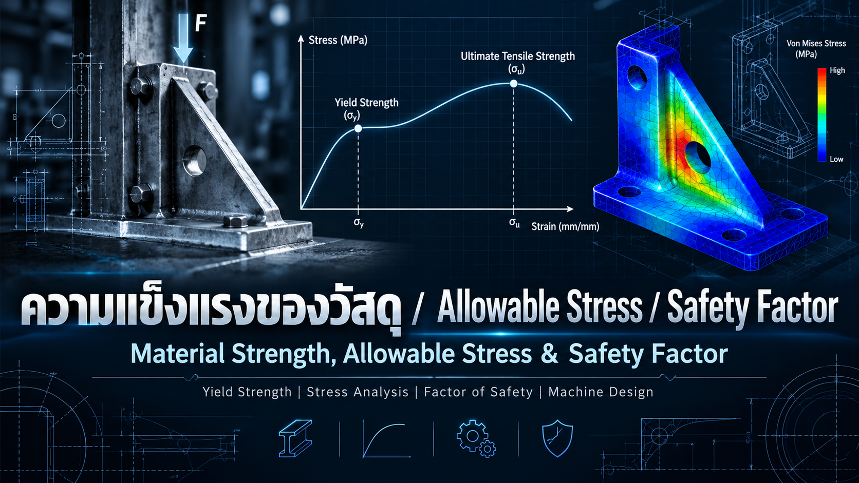
Material Strength, Allowable Stress and Safety Factor: Essential Principles for Mechanical Design
Understanding Yield Strength, Ultimate Tensile Strength, Engineering Stress and Safety Margins in Machine Design, Fixtures and Steel Structures
Mechanical strength is one of the fundamental considerations in industrial machinery and structural component design.
Machine frames, shafts, brackets, fixtures, conveyors and supporting structures must withstand operating loads without unacceptable deformation or failure.
Selecting a material based only on its nominal strength is not sufficient. Engineers must also determine the stresses produced by applied loads, establish appropriate design limits and evaluate relevant failure modes.
Three essential concepts are Material Strength, Allowable Stress and Factor of Safety.
This article explains these principles and provides practical calculations for industrial machine design.
1. What Is Material Strength?
Material Strength describes the ability of a material to withstand applied stresses before reaching a defined limit such as yielding, fracture or another failure condition.
Different materials have different mechanical properties depending on their composition, manufacturing process, heat treatment and operating environment.
Yield Strength
Yield Strength is the engineering stress associated with the onset of plastic deformation under a defined testing method.
For ductile metal components that must remain free from permanent deformation during normal operation, yielding is an important design criterion.
Ultimate Tensile Strength
Ultimate Tensile Strength (UTS) is the maximum engineering tensile stress reached during a tensile test.
For many ductile metals, UTS is higher than Yield Strength.
However, selecting a component based only on UTS may allow unacceptable permanent deformation before fracture occurs.
Compressive Strength
Compressive Strength represents resistance to compressive loading under the relevant failure criterion.
Long and slender members may fail through buckling before reaching their material's compressive strength.
Shear Strength
Shear Strength describes resistance to shear-related failure.
It is relevant to pins, bolts, keys, shafts and mechanical joints.
Fatigue Strength
Fatigue Strength relates to a material's behavior under repeated or fluctuating stresses.
Fatigue damage may develop even when maximum operating stress remains below the material's yield strength.
2. What Are Stress and Strain?
Engineering Stress
For a member subjected to uniform axial loading:
σ = F / A
Where:
σ = Normal stress (MPa)
F = Applied axial force (N)
A = Cross-sectional area (mm²)
A useful unit relationship is:
1 MPa = 1 N/mm²
Engineering Strain
For axial deformation:
ε = ΔL / L₀
Where:
ε = Engineering strain
ΔL = Change in length
L₀ = Original length
For linear elastic behavior, Hooke's Law is:
σ = Eε
Where E is Young's Modulus.
Young's Modulus describes elastic stiffness rather than material strength.
A stronger material does not necessarily have a higher elastic modulus.
3. Common Types of Engineering Stress
| Stress Type | Typical Application |
|---|---|
| Tensile Stress | Tie rods, tension members |
| Compressive Stress | Columns, supports |
| Shear Stress | Pins, bolts, keys |
| Bending Stress | Brackets, beams |
| Torsional Shear Stress | Power transmission shafts |
| Contact Stress | Bearings, gears |
Many industrial machine components experience combined loading.
For example, a rotating shaft may experience bending and torsion simultaneously.
Appropriate combined-stress criteria, such as Von Mises stress for applicable ductile material conditions, may be required.
4. What Is Allowable Stress?
Allowable Stress is a stress limit established under a selected engineering design method or standard.
For a simplified static tensile design based on yielding:
σ_allow = Sy / n
Where:
σ_allow = Allowable stress
Sy = Material yield strength
n = Required design factor
Example
Assume:
Yield Strength = 250 MPa
Required Design Factor = 2.0
Then:
σ_allow = 250 / 2 = 125 MPa
The calculated operating stress should not exceed 125 MPa under the assumptions of this simplified design model.
However, this approach does not replace code-specific design procedures.
Structural steel, pressure equipment and lifting devices may require different strength definitions, partial factors and load combinations.
5. What Is a Factor of Safety?
A Factor of Safety expresses the ratio between a defined failure capacity and the corresponding applied demand.
For a ductile component under uniaxial static tension, using yielding as the criterion:
n_actual = Sy / σ_actual
Where:
n_actual = Calculated factor of safety against yielding
Sy = Yield strength
σ_actual = Calculated operating stress
For example:
Yield Strength = 250 MPa
Actual Stress = 100 MPa
n_actual = 250 / 100 = 2.5
The calculated safety factor against yielding is 2.5.
This result addresses only the failure criterion used in the calculation. It does not automatically verify fatigue, buckling, deflection or connection strength.
6. Design Factor vs. Actual Factor of Safety
The Required Design Factor is established before or during design as the acceptance criterion.
The Actual Factor of Safety is calculated from the component's estimated capacity and demand.
For example:
Required Design Factor = 2.0
Calculated Actual FoS = 2.5
The design meets the specified factor for the particular failure mode being evaluated.
Different failure modes may require separate verification methods and acceptance criteria.
7. Example: Designing a Steel Tension Member
Consider a steel plate subjected to an axial tensile force.
Assume:
Applied Load = 10,000 N
Yield Strength = 250 MPa
Required Design Factor = 2.0
Static axial loading
Uniform stress distribution
No holes or geometric discontinuities
Step 1: Calculate Allowable Stress
σ_allow = 250 / 2 = 125 MPa
Step 2: Calculate Minimum Area
A_required = F / σ_allow
= 10,000 / 125
= 80 mm²
Step 3: Select a Section
Choose a plate with:
Width = 20 mm
Thickness = 5 mm
A = 20 × 5 = 100 mm²
Step 4: Calculate Actual Stress
σ_actual = 10,000 / 100 = 100 MPa
Step 5: Calculate Actual Factor of Safety
n_actual = 250 / 100 = 2.5
The selected section satisfies the simplified yielding criterion.
Additional checks are required if the component includes bolt holes, welds, eccentric loading or other stress concentration features.
8. Example: Bending Stress in a Machine Bracket
Consider a cantilever bracket with:
Applied Force = 500 N
Cantilever Length = 200 mm
Width = 40 mm
Bending Depth = 10 mm
Yield Strength = 250 MPa
Required Design Factor = 2.0
Maximum bending moment:
M = FL = 500 × 200 = 100,000 N·mm
For a rectangular section:
Z = bh² / 6
= (40 × 10²) / 6
= 666.67 mm³
Maximum bending stress:
σ_b = M / Z
= 100,000 / 666.67
= 150 MPa
Allowable stress:
σ_allow = 250 / 2 = 125 MPa
Since 150 MPa exceeds 125 MPa, the section does not satisfy the simplified allowable bending stress criterion.
Possible design modifications include increasing section depth, reducing cantilever length or changing the support arrangement.
Bracket deflection, bolt loads, weld strength and structural connections must also be evaluated.
9. How Should a Safety Factor Be Selected?
There is no universal safety factor suitable for every machine component.
Important considerations include:
Loading Conditions
Static, dynamic, impact and cyclic loading may require different design approaches.
Load Uncertainty
Uncertainty in applied loads should be addressed using an appropriate design methodology.
Material Reliability
Certified material properties and traceable test records improve the reliability of input data.
Manufacturing Conditions
Weld quality, dimensional tolerances, surface finish and production variability affect real component performance.
Failure Consequences
Components whose failure may cause serious injury or major equipment damage require appropriate risk evaluation and design standards.
Applicable Codes
Structural steel, pressure systems and lifting equipment may have prescribed safety or resistance factors.
The appropriate factor must be selected within the context of the relevant standard and failure mode.
10. Applications in Industrial Machinery
Machine Frames
Frames must withstand equipment weight, operating loads and forces generated during machine movement.
Stress, stiffness, vibration and connection strength should all be evaluated.
Jig & Fixture Design
Fixtures may experience clamping forces, cutting loads and mechanical reaction forces.
Locating pins, support blocks and fixture bases must be designed accordingly.
Shaft Design
Shafts may experience combined bending, torsion and axial loading.
Fatigue, stress concentration and critical speeds may also govern the design.
Conveyor Systems
Conveyor supports must carry structural dead loads, operating loads and moving materials.
Deflection and vibration may be as important as material yielding.
Steel Brackets
Machine brackets require verification of bending, shear, fastener strength, welds and support conditions.
Lifting Equipment
Cranes, lifting beams and hoist structures require specialized design standards and safety verification beyond basic allowable stress calculations.
11. Why a High Safety Factor Does Not Guarantee Safety
A component with a high factor of safety against yielding may still fail through other mechanisms.
Buckling: Slender compression members may become unstable.
Fatigue: Repeated loading can produce progressive cracking.
Excessive Deflection: A structure may deform too much for its intended function.
Resonance: Dynamic excitation may amplify machine vibration.
Stress Concentration: Holes, shoulders, notches and sharp corners can produce elevated local stresses.
Connection Failure: Bolts, pins, welds and supporting structures may fail before the main component reaches its strength limit.
A complete engineering assessment must address all relevant limit states.
12. Finite Element Analysis (FEA) in Machine Design
Finite Element Analysis can help evaluate complex components subjected to mechanical loads.
Depending on the model and software capabilities, FEA may be used to investigate:
Stress distributions
Von Mises stress
Displacement and deformation
Contact pressure
Buckling behavior
Natural frequencies
Fatigue behavior
Simulation results depend on material models, mesh quality, applied loads, boundary conditions and connection definitions.
FEA should be verified using engineering calculations, convergence checks, testing or other appropriate methods.
13. Relevant Engineering Standards
ISO 6892-1 – Metallic Materials Tensile Testing
Defines procedures for determining mechanical properties of metallic materials at room temperature.
ISO 12100 – Safety of Machinery
Provides principles for machinery risk assessment and risk reduction.
AISC 360 – Structural Steel Design
Includes requirements for steel structures using ASD and LRFD design methods.
EN 1993 – Eurocode 3
Provides structural steel design rules based on limit-state principles and relevant partial factors.
ASME Boiler and Pressure Vessel Code
Provides requirements and material data for equipment within the applicable pressure equipment code scope.
Each standard has a defined application and should not be treated as universally applicable to all machine components.
14. Common Engineering Design Mistakes
Using Ultimate Strength Instead of Yield Strength
This may lead to an inappropriate failure criterion for components that must remain free from permanent deformation.
Using the Same Safety Factor for Every Component
Different loading conditions and failure consequences require appropriate engineering evaluation.
Ignoring Deflection
A component may remain below yield stress while still deforming excessively.
Ignoring Dynamic or Impact Loads
Actual operating conditions may differ significantly from static design assumptions.
Ignoring Stress Concentrations
Bolt holes, grooves and geometric transitions can affect local stresses.
Failing to Check Welds and Fasteners
The connection may govern the overall assembly strength.
Relying on Unverified Simulation Results
Incorrect boundary conditions or material properties can produce misleading conclusions.
15. Frequently Asked Questions
What Is the Difference Between Yield Strength and Tensile Strength?
Yield Strength refers to the onset of plastic deformation under the specified definition, while Ultimate Tensile Strength is the maximum engineering tensile stress during a tensile test.
How Is Allowable Stress Calculated?
For a simplified static yielding criterion, allowable stress can be estimated by dividing yield strength by the required design factor. Code-based design may use different procedures.
What Does a Safety Factor of 2 Mean?
For a yield-based uniaxial stress calculation, it means the ratio of yield strength to calculated operating stress is 2.
It does not guarantee safety against all possible failure modes.
Is a Higher Safety Factor Always Better?
Not necessarily. Excessive conservatism may increase cost and weight without addressing governing failure mechanisms.
Is Yield Strength Enough for Machine Design?
No. Stiffness, fatigue, buckling, dynamic response and connection strength may also need verification.
Is FEA Required for Every Machine Component?
Not always. Simple components can often be evaluated using accepted analytical methods, while complex structures may benefit from verified numerical analysis.
16. Conclusion
Material Strength, Allowable Stress and Factor of Safety are fundamental principles of reliable mechanical engineering design.
Material Strength describes a material's ability to withstand defined failure conditions.
Allowable Stress establishes a stress limit under a selected design method.
The Factor of Safety expresses a capacity-to-demand relationship for a particular failure mode.
Effective machine design requires these concepts to be combined with realistic load analysis, material selection, stiffness verification, fatigue evaluation and appropriate engineering standards.
The best engineering design is not necessarily the heaviest or the one with the largest safety factor, but the design that achieves the required function, reliability and safety at a reasonable overall cost.
AC DESIGN AND DEVELOPMENT – Mechanical Design & Industrial Engineering Solutions
AC DESIGN AND DEVELOPMENT CO., LTD. provides custom industrial engineering and manufacturing solutions, including:
Automation Machine Design and Manufacturing
Jig & Fixture Design and Manufacturing
Conveyor Systems
Custom Machine Parts
Industrial Steel Structures
Custom Engineering Solutions
We focus on practical engineering solutions that support manufacturing efficiency, reliable mechanical operation and appropriate material selection.
Engineering and Industrial Manufacturing Services Across Thailand
Website: https://acdesignanddevelopment.com/
Tel: +66 82-210-0792
Technical Disclaimer: The calculations are simplified educational examples. Actual structural and machine design must be verified using validated material data, applicable engineering standards and appropriate professional engineering assessment.