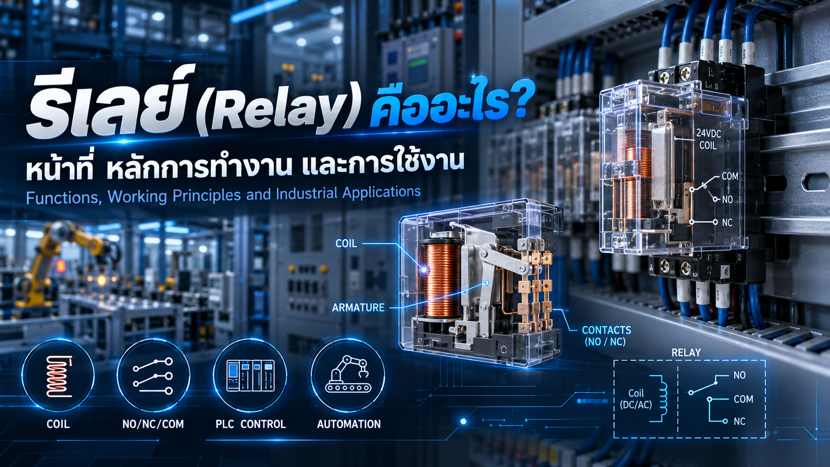
What Is a Relay? Working Principles, Types and Industrial Applications
Understanding electrical relays, NO/NC contacts, PLC interfacing and their role in industrial automation systems
Electrical relays are essential components in industrial automation, electrical control panels and machinery control systems.
Although relays are relatively small devices, they play an important role in switching electrical circuits, controlling external equipment and interfacing programmable logic controllers (PLCs) with industrial loads.
Understanding how relays work is fundamental for electrical engineers, automation technicians, machine designers and maintenance personnel.
This article explains the basic operating principles of relays, their main components, contact configurations, different types, industrial applications and important selection considerations.
1. What Is an Electrical Relay?
A relay is an electrically operated switching device used to control the opening and closing of electrical circuits.
In an electromechanical relay, an electrical signal energizes a coil, generating a magnetic field that moves an internal mechanical mechanism.
This movement changes the state of electrical contacts, allowing the relay to switch another circuit.
For example, a PLC with a compatible 24VDC output can energize a 24VDC relay coil. The relay contacts can then switch a separate electrical load, provided the contact ratings are suitable for the application.
2. Main Functions of Electrical Relays
Electrical Switching
Relays control the ON/OFF state of electrical loads such as indicator lights, solenoid valves and control circuits.
Circuit Isolation
An appropriately rated electromechanical relay can provide electrical separation between its control coil and contact circuits.
Signal Interfacing
Relays can interface control signals with circuits operating at different voltages or requiring different switching characteristics.
Multiple Circuit Control
Relays with multiple contacts allow one control signal to operate several circuits.
Control Sequence Management
Relays can support machine operating sequences, conventional interlocking circuits and automation control logic.
3. Main Components of an Electromechanical Relay
An electromechanical relay typically contains the following components:
Coil: An electromagnetic winding that generates a magnetic field when energized.
Magnetic Core: Concentrates and directs the magnetic field.
Armature: A movable mechanical component operated by the magnetic field.
Contacts: Electrical switching elements that open or close the load circuit.
Return Spring: Returns the mechanism to its normal position when the coil is de-energized in conventional monostable relays.
Terminals: Provide electrical connections for the coil and contact circuits.
4. How Does a Relay Work?
A conventional monostable electromechanical relay has two basic operating states.
Coil De-energized (OFF)
When the coil is not energized, the mechanism remains in its normal position.
Normally Open (NO) contacts remain open.
Normally Closed (NC) contacts remain closed.
Coil Energized (ON)
When the specified voltage is applied to the coil, the resulting magnetic field moves the armature.
Normally Open (NO) contacts close.
Normally Closed (NC) contacts open.
When the coil is de-energized, the relay normally returns to its original position.
Latching relays operate differently because they can maintain their switching state after the control signal is removed.
5. Understanding NO, NC and COM Contacts
NO – Normally Open
A Normally Open contact remains open in the relay's normal state and closes when the relay operates.
It is commonly used for activating equipment only when a control signal is present.
NC – Normally Closed
A Normally Closed contact remains closed in the normal state and opens when the relay operates.
NC contacts are frequently used in status monitoring and conventional control interlocking circuits.
COM – Common
The Common terminal is part of a changeover contact arrangement.
Depending on the relay state, COM connects to either NC or NO.
Typical IEC-style terminal examples include:
| Terminal | Function |
|---|---|
| A1 / A2 | Relay Coil |
| 11 | Common Contact |
| 12 | Normally Closed |
| 14 | Normally Open |
| 21 | Second Common |
| 22 | Second Normally Closed |
| 24 | Second Normally Open |
Terminal arrangements vary between manufacturers and models. Always confirm the actual wiring diagram before installation.
6. Types of Relays Used in Industrial Automation
Electromechanical Relay (EMR)
Electromechanical relays use a coil-driven mechanical contact system.
They are commonly found in control panels, PLC interfaces, machine control circuits and solenoid control applications.
Their advantages include simple operation, multiple contact configurations and the ability to switch suitable AC or DC loads.
However, their mechanical contacts experience wear over time.
Solid State Relay (SSR)
A Solid State Relay uses semiconductor devices to switch electrical loads without mechanical contact movement.
SSRs are commonly used for:
Heater control
Temperature regulation
High-frequency switching
Applications requiring silent operation
Their main advantages include quiet operation and the absence of mechanical contact wear.
However, SSRs require careful consideration of heat dissipation, off-state leakage current and compatibility with AC or DC loads.
Safety Relay
Safety Relays are designed for safety-related control functions in machinery.
Typical applications include emergency stop circuits, safety door monitoring and light curtain systems.
Unlike ordinary control relays, safety devices may incorporate redundancy, monitoring and fault detection functions.
Machine safety systems must be designed according to the required safety performance determined through risk assessment.
Timer Relay
Timer Relays provide controlled switching delays, such as ON-delay and OFF-delay operation.
They are used in machine sequencing and industrial timing applications.
Latching Relay
Latching Relays maintain their contact state after the control signal is removed.
They can be useful when maintaining a control state without continuous coil energization is required.
7. How Relays Work with PLCs
Programmable Logic Controllers are widely used to control industrial machinery.
A relay can act as an intermediate switching device between a PLC output and an external load.
Example: PLC-Controlled Solenoid Valve
Consider a machine using a PLC and a solenoid-operated pneumatic valve.
A typical operating sequence is:
A sensor detects a workpiece.
The PLC evaluates the programmed conditions.
The PLC activates a compatible relay coil circuit.
The relay's NO contact closes.
Power is supplied to the solenoid valve.
The valve operates according to its design.
When the PLC removes the output command, the relay returns to its normal state.
The actual wiring depends on PLC output characteristics, relay coil current, electrical polarity and load protection requirements.
Some PLC outputs can drive suitable loads directly, so an intermediate relay is not always necessary.
8. Relay vs. Contactor: What Is the Difference?
Relays and contactors are both electrically operated switching devices, but their typical applications differ.
| Feature | Relay | Contactor |
|---|---|---|
| Primary Application | Control and signal switching | Power-load switching |
| Common Loads | Indicators, solenoids, control coils | Motors, heaters, power circuits |
| Contact Configuration | NO, NC, Changeover | Main and auxiliary contacts |
| Selection Criteria | Contact ratings and load characteristics | Load power and utilization category |
| Typical Accessories | Relay socket, surge suppressor | Overload protection and auxiliary contacts |
For motor starting applications, a properly rated motor contactor or motor starter is generally more appropriate than a standard control relay.
9. How to Select the Right Relay
Proper relay selection requires evaluating the electrical and environmental requirements of the application.
Coil Voltage
Select the correct coil voltage and current type, such as 24VDC or 230VAC.
Contact Ratings
Verify that the relay contacts are rated for the actual load voltage, current and switching characteristics.
A relay marked 10A may not support every type of 10A load. Inductive loads, DC switching and high inrush currents require particular attention.
Contact Configuration
Select the required number and type of contacts, such as 1CO, 2CO or 4CO.
Switching Frequency
Determine how often the relay will operate. High-frequency switching may favor a suitably rated SSR.
Electrical Durability
Evaluate expected contact life under actual load conditions rather than relying only on mechanical life specifications.
Environmental Conditions
Consider installation temperature, vibration, humidity and enclosure conditions.
Surge Protection
Inductive coils can generate voltage transients when switched off.
Suitable suppression devices, such as flyback diodes for DC coils or properly rated RC snubbers and varistors, can reduce these effects.
However, suppression circuits can change relay release times and must be selected carefully.
10. Common Relay Problems and Troubleshooting
Relay Does Not Energize
Possible causes include incorrect coil voltage, a damaged coil, loose connections or a control signal failure.
Relay Operates but the Load Remains OFF
Check for contact damage, missing load supply voltage, wiring defects or faulty external equipment.
Relay Chatters
Unstable or insufficient coil voltage may cause repeated mechanical switching.
Contacts Become Welded
Excessive current, inrush current or unsuitable inductive-load switching can damage relay contacts.
Excessive Heating
Possible causes include overloads, improper wiring, poor connections or incorrect operating conditions.
Before performing inspection or maintenance, disconnect and isolate all relevant electrical sources, follow lockout/tagout procedures and verify the absence of hazardous voltage.
11. Frequently Asked Questions
Can a 24VDC Relay Control a 220VAC Load?
Yes, an appropriately designed electromechanical relay with a 24VDC coil can switch a separate 220VAC circuit if the contact ratings, insulation requirements and load characteristics are suitable.
Why Are Relays Used with PLCs?
Relays can provide intermediate switching, additional contacts and electrical separation between suitable control and load circuits.
What Is the Difference Between NO and NC?
NO contacts are open in the normal state, while NC contacts are closed in the normal state.
Are Solid State Relays Better Than Mechanical Relays?
Neither type is universally better. The correct choice depends on switching frequency, load characteristics, thermal requirements, leakage current and application conditions.
Can an Ordinary Relay Be Used as an Emergency Stop Safety Device?
An ordinary relay alone should not be relied upon to perform a machinery safety function. Appropriate safety-rated devices and architecture must be selected according to the risk assessment and required safety performance.
12. Conclusion
Electrical relays are fundamental components of industrial electrical and automation control systems.
They provide a practical way to switch circuits, interface control signals and coordinate machine operations.
Understanding relay coils, NO/NC contacts, electrical ratings and application requirements allows engineers and technicians to design more reliable and maintainable control systems.
Correct selection and installation are essential to achieving safe, consistent and efficient machinery operation.
AC DESIGN AND DEVELOPMENT – Industrial Automation Solutions
AC DESIGN AND DEVELOPMENT CO., LTD. provides customized engineering and industrial manufacturing services, including:
Automation Machine Design and Manufacturing
Jig & Fixture Systems
Conveyor Systems
Custom Machine Parts
Industrial Steel Structures
Custom Engineering Solutions
Our focus is on developing practical engineering solutions that support manufacturing efficiency, quality and operational reliability.
Engineering and Automation Solutions Across Thailand
Website: https://acdesignanddevelopment.com/
Tel: +66 82-210-0792
Technical Disclaimer: This article is intended for general educational purposes. Electrical equipment must be selected, installed, tested and maintained according to manufacturer specifications and applicable electrical safety requirements.